The auxiliary switch is a critical ancillary component within the operating mechanism of Medium/High Voltage (MV/HV) circuit breakers. It is responsible for converting the mechanical state of the main circuit breaker into the electrical signals required by the secondary control circuit, forming the foundation for reliable electrical interlocking and status monitoring. This article provides an in-depth analysis of the technical principles employed by auxiliary switches, such as precision mechanical linkage and photoelectric isolation, and discusses effective strategies to mitigate practical operational challenges—including environmental factors, installation errors, and long-term aging—to ensure the sustained reliability and accuracy of its signal output.
Core Function and Value of Auxiliary Switch
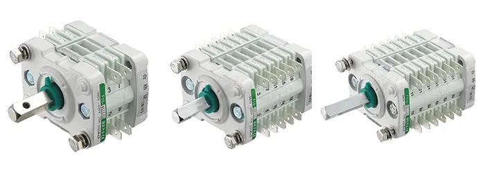
In MV/HV power transmission and distribution systems (e.g., 10 kV to 40.5 kV class), the auxiliary switch functions as a crucial accessory to the main circuit breaker (such as Vacuum Circuit Breakers or SF6 Circuit Breakers). Its core value lies in converting the main switch’s opening/closing actions into accurate electrical or digital signals essential for remote control, protection systems, and status monitoring. The reliability of this signal is paramount for the correct execution of grid interlocking protection logic and the accuracy of operational decisions.
Core Technologies for Accurate Auxiliary Switch Status Mapping
To overcome the limitations of traditional mechanical structures in high-voltage, high-electromagnetic environments, modern MV/HV auxiliary switch products integrate several advanced technologies to ensure signal real-time performance, anti-interference capability, and high reliability.
1. Precision Mechanical Linkage: The Foundation of High-Accuracy Mapping
Precision mechanical linkage is the physical basis for the auxiliary switch’s electrical signal output. Utilizing high-accuracy connecting rods, transmission shafts, or customized cam mechanisms, the auxiliary switch’s moving and stationary contacts achieve millisecond-level synchronization with the main switch’s trip/close components. A key design requirement is ensuring high-precision mapping of the operating stroke. This means the make-and-break timing of the auxiliary contacts must be precisely synchronized with the main contact operation, providing the most reliable mechanical assurance for complex electrical interlocking systems.
2. Photoelectric Isolation Technology: The Anti-Interference Strategy for Signal Transmission
In high-voltage, high-electromagnetic environments, induced voltages and electromagnetic noise can severely interfere with traditional electrical signal transmission. Photoelectric coupling technology is the key to resolving this issue.
-
Operating Mechanism: It uses an optical signal as the information carrier, converting the main switch’s mechanical action into a light signal, which is then transformed back into an electrical signal by a photo-converter on the isolated side.
-
Value Proposition: This design achieves complete electrical isolation (Galvanic Isolation) between the control and primary circuits. This significantly enhances the auxiliary switch signal’s Electromagnetic Interference (EMI/EMC) immunity, ensuring the stability and reliability of the secondary control signal.
3. Smart Sensor Integration: Advancing Towards Predictive Maintenance
In the trend towards intelligent systems, some high-end or customized auxiliary switches may integrate micro-sensors (e.g., position, temperature) or embedded microprocessors. This capability extends their function from mere status indication to data collection and trend analysis for operational status. In the future, by collecting operational parameters such as the number of operations, speed profile, and mechanism stored energy, and combining this with data analytics, the maintenance system is expected to predict potential mechanical wear or aging trends in the circuit breaker mechanism. This trend-based condition-based maintenance (CBM) model will help mitigate the risk of unplanned outages and optimize asset management.
Technical Pathways for Ensuring Sustainable Auxiliary Switch Reliability
Although the technical principles of the MV/HV auxiliary switch are quite mature, its performance and indication accuracy in practical grid applications remains susceptible to various external factors, including environmental conditions, installation quality, and long-term operation. Consequently, established solutions must be incorporated into the technical design, supported by rigorous manufacturing process control, to guarantee the switch’s continued reliability throughout its entire lifecycle.
Sustainable auxiliary switch reliability primarily addresses the following three challenges:
-
Environmental Factors and Protection: Auxiliary switch performance is vulnerable to environmental factors such as temperature, humidity, and vibration. For instance, high temperatures can cause material expansion, affecting the accuracy of the mechanical linkage, while humid conditions may degrade insulation performance. Therefore, during product design, material selection, and manufacturing, engineers must fully account for the anticipated operating environment and implement protective measures like high/low-temperature resistance, moisture proofing, and reinforced sealing to ensure stable, long-term signal output.
-
Installation and Commissioning Precision Control: The accuracy of the auxiliary switch is highly dependent on correct field installation and precise commissioning. Improper installation or calibration errors can directly lead to timing discrepancies between the auxiliary switch and the main switch operation, severely compromising status indication accuracy. Consequently, installation must strictly adhere to the manufacturer’s guidelines, and the commissioning phase requires careful validation of key parameters to ensure the auxiliary switch’s action is perfectly synchronous with the main switch’s operation.
-
Maintenance and Aging Management in Long-Term Operation: Inevitable mechanical wear, component aging, and dust accumulation during long-term service pose a challenge to the switch’s performance and lifespan. To maintain optimal operational status, a rational and rigorous periodic maintenance plan is recommended. Maintenance procedures should encompass regular inspection, cleaning, and necessary component replacement based on operating conditions, effectively managing equipment aging risks.
Conclusion
The MV/HV auxiliary switch is an indispensable component for status indication and signal transmission within the circuit breaker operating mechanism. By utilizing mature technologies like precision mechanical linkage and photoelectric isolation, the auxiliary switch effectively secures the reliability and anti-interference capability of the secondary control circuit signal, which is fundamental for correct electrical interlocking logic execution. Although its core function is precise status mapping, the technical integration and application potential of the auxiliary switch continue to expand alongside the power system’s progression toward digitalization. For the global electrical equipment industry, sustained focus on optimizing the long-term reliability and precision of the auxiliary switch remains a critical step toward enhancing the overall performance of MV/HV equipment.