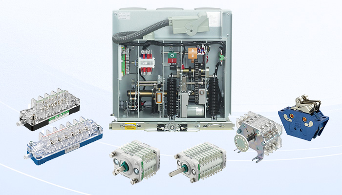
The auxiliary switch is a critical component within medium voltage switchgear, installed inside the operating mechanism. Its core function is to output the working status signal of the switching device and participate in the control circuit and protection interlocking. During operation, the auxiliary switch may encounter several typical failure modes, such as contact bounce, abnormal increase in contact resistance, and failure of time-delay contacts to switch. For the practical operation and maintenance of MV switchgear, a deep understanding of these fault causes and their corresponding technical solutions is vital. The operational reliability of the auxiliary switch directly impacts the safety and stability of the entire switching system.
Auxiliary Switch Typical Fault Analysis
1) Auxiliary Switch Contact Bounce
During the operation of the MV switch, the status signal emitted by the auxiliary switch exhibits an abnormal momentary change. For example, during the breaker tripping action, the “moving” signal should be continuous, but it momentarily generates an incorrect signal (such as “closed” status) inconsistent with the actual state, or an occasional momentary signal jitter occurs when the switch is stationary. This phenomenon is known as contact bounce.
Cause Analysis: Mechanical Structure and Tolerance
Some auxiliary switches are designed with a high-speed commutation device (usually employing a torsion spring energy release principle) to quickly interrupt high-current control circuits.
If the clearance of the auxiliary switch transmission central shaft is excessive or the machining precision of components is insufficient during the high-speed commutation process, the central shaft may experience slight movement. This movement can lead to momentary, unintended electrical contact at the critical switching position, resulting in a transient incorrect signal of extremely short duration, which is the bounce phenomenon.
Solution: Improve Mechanical Component Precision
The key to eliminating contact bounce signals lies in improving the manufacturing precision of the auxiliary switch transmission components and strictly controlling the rotational central shaft’s clearance to ensure the mechanism’s stability during high-speed movement. Furthermore, the viscosity of the lubricant and assembly errors must be managed.
2) Abnormal Increase in Contact Resistance
The resistance value between the auxiliary switch moving and stationary contacts (i.e., contact resistance) shows an abnormal increase, far exceeding the specified low resistance standard. Increased contact resistance leads to a greater voltage drop across the control circuit, which affects the reliability of the operating mechanism’s action.
Cause Analysis: Electrical Erosion and Environmental Factors
Analysis of faulty contacts often reveals significant electrical arc erosion and oxidation on their surfaces.
The main factors contributing to increased contact resistance include:
-
Breaking Current: The electric arc generated when the auxiliary switch interrupts the control circuit current causes long-term damage and burning of the contact material.
-
Environmental Impact: In humid, salt spray, dusty, or other harsh operating environments, the electrical corrosion and oxidation of the contact surface are accelerated, leading to the formation of deposits.
-
DC Circuit: Under DC voltage conditions, arc extinguishing is more difficult, and the degree of electrical corrosion to the contacts is particularly severe.
These surface damages and deposits are the direct causes of abnormally high high contact resistance.
Solution: Optimize Contact Design and Wiring Method
-
Optimize Design: Improve the arc suppression structure, contact material, and surface treatment process of the auxiliary switch contacts to enhance their resistance to arc erosion and breaking capacity.
-
Wiring Reinforcement: It is recommended to use a dual-series dual-parallel connection method for auxiliary contacts. This wiring method effectively distributes the breaking current and provides redundancy, thereby improving the reliability of the auxiliary switch in the operating circuit.
3) Failure of Time-Delay Contacts to Switch
Some auxiliary switches are equipped with time-delay contacts to implement timed sequence actions within the control circuit. The fault manifests as the failure of the time-delay contacts to switch according to the designed sequence after the MV switch completes its operation, resulting in the failure of related tripping or control circuit functions.
Cause Analysis: Insufficient Mechanical Trigger Margin
The switching of the time-delay contact relies on a mechanical time-delay trigger mechanism, which requires the auxiliary switch central shaft to rotate to a specific mechanical trigger angle to be activated.
If there is an initial adjustment deviation in the auxiliary switch transmission chain, the actual rotation angle of the central shaft, when the mechanism completes its action, may not reach or barely reach the critical trigger point. This condition, known as insufficient trigger angle margin, prevents the reliable triggering of the time-delay device, leading to the contact failure to switch.
Solution: Increase Angle Margin
Without affecting the other movement characteristics of the entire transmission chain, precise adjustment of the auxiliary switch transmission component position should be performed to slightly offset the initial rotation angle of the auxiliary switch central shaft. The goal of this measure is to effectively increase the trigger angle margin of the time-delay contact, ensuring its switching reliability.
Summary and Recommendations
Based on the in-depth analysis of the three typical failure modes of medium voltage auxiliary switches, we summarize the following key conclusions and corresponding technical improvement directions:
For the contact bounce phenomenon, the main root cause lies in manufacturing quality deficiencies and insufficient mechanical precision in auxiliary switches equipped with high-speed commutation devices. Therefore, solutions should focus on improving component precision and optimizing the assembly process.
The fault of abnormal contact resistance increase, especially under DC low voltage and harsh environmental conditions, requires heightened attention. It is recommended to enhance the contact’s breaking capacity and operational reliability by improving the contact’s arc suppression structure and material, combined with adopting the dual-series dual-parallel wiring method.
Concurrently, to resolve the issue of time-delay contacts failing to switch, the technical focus is on increasing the time-delay contact trigger angle margin. Reliable triggering of the mechanical mechanism is ensured through precise adjustment of the transmission chain, thereby effectively enhancing the auxiliary switch’s sequence switching performance.
In conclusion, the stable operation of the auxiliary switch is the cornerstone for the reliability of medium voltage distribution networks. The above fault analysis and technical recommendations—addressing the three core dimensions of mechanical precision, electrical contact, and sequence control—provide systematic reference and maintenance guidance for MV switchgear manufacturers and operating personnel, aiming to ensure the long-term safety and efficient operation of the power system through detailed management and preventive measures.