In modern power systems, auxiliary switches serve as crucial sensing and control components within medium/high voltage (MV/HV) switchgear (such as circuit breakers and disconnectors). Their performance directly influences the overall system’s operational stability, safety, and automation levels. Rated voltage and rated current are two core technical indicators that not only affect the selection and design of switchgear but also profoundly determine the power system’s operational reliability, efficiency, and equipment lifespan. A deep understanding of the specific impact of auxiliary switch rated voltage and current on MV/HV power systems, along with key considerations in their selection and full lifecycle management, is crucial for ensuring their efficient operation.
Impact of Auxiliary Switch Rated Voltage
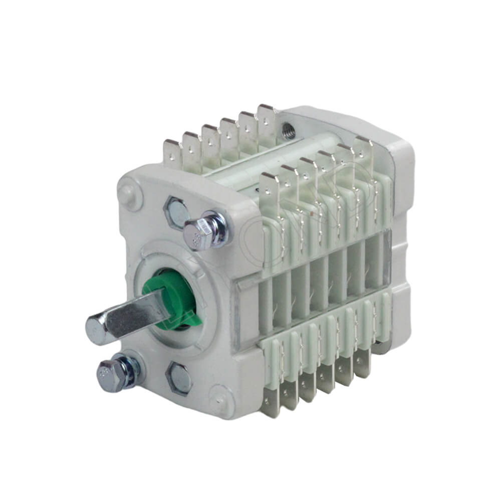
Rated voltage refers to the maximum voltage an auxiliary switch can continuously and safely operate under normal working conditions. This parameter is closely related to the insulation performance of the switchgear, and its correct selection and application are critical for the power system.
Insulation Safety and Breakdown Risk: Rated voltage defines the withstand capability of the auxiliary switch’s internal insulating materials, including creepage distance, electrical clearance, and dielectric strength of solid insulation. When the actual system voltage exceeds the auxiliary switch’s rated voltage, the insulating materials will be subjected to too much electric field stress, which may lead to partial discharge, accelerated insulation aging, or even insulation breakdown and flashover, thereby endangering personnel safety and equipment operation.
System Matching and Coordination: The rated voltage of the auxiliary switch must be adequately coordinated with the nominal system voltage, operating voltage range, and potential transient overvoltages (e.g., switching overvoltage, lightning overvoltage) of the power system in which it is installed. Incorrect voltage matching can cause the auxiliary switch to maloperate or be damaged during system voltage fluctuations, affecting the correct execution of control circuits and potentially triggering unnecessary protection actions, which can impact grid stability.
Resource Utilization and Economic Efficiency: While selecting an auxiliary switch with an excessively high rated voltage provides increased safety margin, it typically implies higher costs and larger dimensions, which may lead to unnecessary resource waste. Conversely, choosing an auxiliary switch with a rated voltage below the actual operating voltage poses safety hazards. Therefore, a rational selection of rated voltage is important for balancing safety, performance, and economic benefits.
Long-term Reliability: Even within the rated voltage range, continuous voltage stress can affect insulating materials. High-quality auxiliary switches are designed to consider long-term voltage withstand capability, ensuring that their insulation performance does not significantly degrade due to normal operating voltage throughout their expected lifespan.
.jpg)
Impact of Auxiliary Switch Rated Current
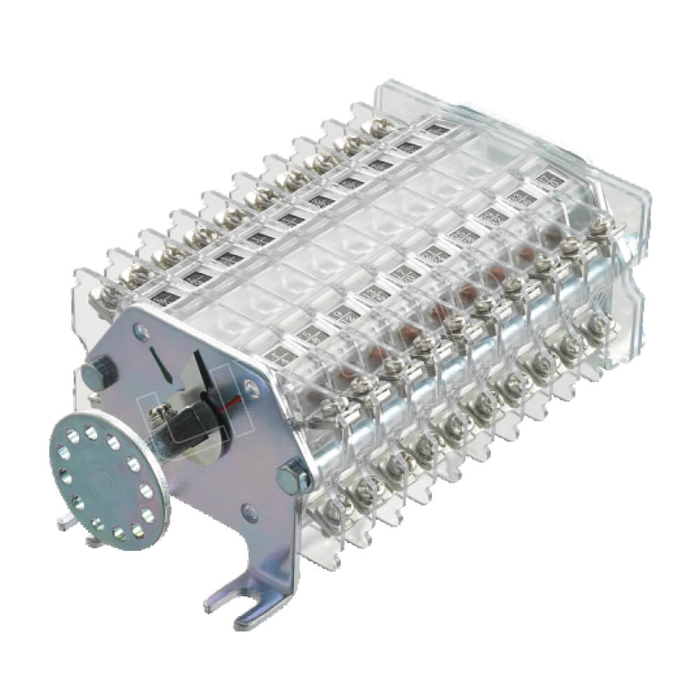
Rated current refers to the maximum current that the contacts of an auxiliary switch can safely carry under long-term continuous operation, with its temperature rise not exceeding specified limits. This parameter primarily relates to the thermal and dynamic stability of the contacts.
Thermal Effects and Contact Temperature Rise: When the actual current flowing through the auxiliary switch contacts approaches or exceeds its rated current, the contacts and connection points will generate heat due to the Joule effect (P=I2R). Too much temperature rise can accelerate contact material oxidation, creep deformation, increase contact resistance, and even lead to contact welding, causing the auxiliary switch to fail to open or close properly, thereby losing control and signaling functions.
Contact Wear and Electrical Life: Auxiliary switch contacts generate electric arcs during opening and closing operations. Especially when switching inductive or capacitive loads, the arc energy can be substantial, leading to burning and wear of the contact material. Rated current directly correlates with the switch’s “breaking capacity” and “making capacity”—the ability of contacts to effectively break and make specified currents. Frequent or high-current switching accelerates contact degradation, shortening the auxiliary switch’s electrical life.
Short-Time Withstand Capability: In addition to continuous operating current, auxiliary switches also need to withstand instantaneous high currents during short-circuit faults. Rated short-time withstand current (or rated dynamic-thermal withstand current) is a measure of the auxiliary switch’s ability for its contacts and conductive parts to not melt or suffer mechanical damage within a very short period (e.g., 1 second) when subjected to a short-circuit current. This indicator is vital for ensuring the integrity of the auxiliary switch under system fault conditions.
Modern Design and Optimization: Modern auxiliary switches have undergone research in contact material selection (e.g., silver alloys, silver-tungsten alloys), contact structure design (e.g., multi-point contacts, self-cleaning contacts), and heat dissipation path optimization to enhance their rated current carrying capacity and short-circuit withstand capability. Some intelligent auxiliary switches even incorporate built-in temperature sensors for real-time monitoring and early warning of contact temperature rise.
Synergistic Impact of Auxiliary Switch Rated Parameters and Environmental Factors
Rated voltage and rated current are not independent parameters; they interact with each other in the actual operation of auxiliary switches and are constrained by external environmental factors.
Load Type and Power Factor: Different types of loads (resistive, inductive, capacitive) affect the phase relationship between the current flowing through the auxiliary switch and the voltage (i.e., power factor). Particularly when switching inductive loads, high overvoltages may be generated during interruption, while large inrush currents may occur during closing. This simultaneously challenges the auxiliary switch’s rated voltage withstand capability and its current breaking/making capacity.
Harmonic Impact: Non-linear loads in power systems (e.g., inverters, EV charging stations) generate harmonics, leading to current waveform distortion. Harmonic currents increase the RMS current through the auxiliary switch contacts, resulting in additional temperature rise and accelerated contact aging. Harmonic voltages can also cause insulation media to endure higher instantaneous voltage stresses. Therefore, in applications with complex harmonic environments, the rated parameters of auxiliary switches may need to be derated, or higher-grade products should be selected.
Environmental Constraints:
Temperature: High temperatures reduce the dielectric strength of auxiliary switch insulating materials and increase conductor resistance, leading to a further rise in temperature and thus lowering its rated current carrying capacity. Low temperatures can affect the flexibility of mechanical parts and the performance of lubricants.
Humidity and Condensation: High humidity or condensation can reduce surface creepage distances, lower insulation resistance, and increase the risk of flashover and breakdown. It also accelerates corrosion of metal components, affecting contact performance.
Altitude: At high altitudes, air density decreases, leading to a reduction in the dielectric strength of insulating media, requiring correction of the auxiliary switch’s rated voltage.
Pollution: Adherence of contaminants such as dust, salt spray, and chemical corrosive substances to insulation surfaces can form conductive pathways, reducing insulation strength and increasing the risk of flashover.
Material and Encapsulation Technologies Response: To address these synergistic impacts and environmental challenges, auxiliary switch manufacturers continuously develop new materials and encapsulation technologies. For example, using special silver alloy contact materials (e.g., AgNi, AgSnO2) to improve arc erosion resistance; and employing sealed designs with inert gas filling (e.g., nitrogen) to isolate contacts from the external environment, effectively preventing oxidation and contamination, thereby ensuring long-term stable operation of contacts in harsh conditions.
Standardized Selection and Full Lifecycle Management of Auxiliary Switches
Understanding the impact of rated voltage and current helps in making informed decisions throughout the entire lifecycle of auxiliary switches, from selection and installation to operation and maintenance.
Standardized Selection Principles:
Matching Main Circuit Parameters: The rated voltage, rated current, and rated short-time withstand current of the auxiliary switch must strictly match the operating and fault parameters of the main circuit of the associated MV/HV switchgear, with sufficient safety margins.
Considering Auxiliary Control Requirements: Select an auxiliary switch with appropriate contact capacity and switching levels based on the voltage class, current magnitude (e.g., operating coil current, indicator lamp current), and load type of the control circuit.
Environmental Adaptability: Consider the environmental conditions of the installation site (temperature, humidity, altitude, pollution level, vibration, etc.), and select products with corresponding ingress protection (IP ratings) and environmental adaptability certifications.
Mechanical Characteristics and Mounting Method: Confirm that the auxiliary switch’s mechanical life, operating characteristics (e.g., travel, time), actuation method (direct-acting, cam-operated, gear-driven), and mounting dimensions/method are compatible with the circuit breaker mechanism.
Compliance with International Standards: Ensure that the selected product complies with relevant international standards such as IEC and IEEE, which typically indicates that the product has undergone rigorous testing and certification, ensuring higher reliability and interchangeability.
Full Lifecycle Management:
Correct Installation and Commissioning: Strictly follow the manufacturer’s installation manual, ensuring correct and secure wiring, smooth mechanical linkage without jamming, and verifying signal transmission accuracy and operation timing during the commissioning phase.
Regular Inspection and Maintenance: Conduct periodic visual inspections, cleaning, contact condition checks, wiring tightness verification, and operational flexibility tests on auxiliary switches. For critical parameters like contact resistance and operating time, regular calibration using professional test equipment should be performed.
Data Monitoring and Predictive Maintenance: Integrate Internet of Things (IoT) technology by deploying sensors to real-time monitor the auxiliary switch’s operating status (e.g., contact temperature rise, number of operations, spring condition) and upload data to a cloud platform for big data analysis. Utilize AI algorithms for in-depth data mining to predict potential faults, transitioning from traditional periodic maintenance to condition-based predictive maintenance, thereby achieving more precise and efficient operation and maintenance.
Asset Management Optimization: Through full lifecycle data management of auxiliary switches, optimize spare parts inventory, extend equipment operating life, reduce total cost of ownership (TCO), and enhance the overall efficiency of grid assets.
Conclusion
The rated voltage and current of auxiliary switches, as their most core technical parameters, have an impact on the safety, stability, and efficient operation of power systems. An understanding of the intrinsic meaning of these parameters, their synergistic effects, and environmental constraints is important to ensuring correct auxiliary switch selection and proper application.
Through standardized selection, installation and commissioning, and refined management throughout the entire lifecycle (especially by integrating intelligent monitoring and predictive maintenance technologies), the performance advantages of auxiliary switches can be maximized, and operational risks mitigated. As smart grids continue to develop, the trend towards intelligent, digital, and maintenance-free auxiliary switches will become more pronounced. In the future, auxiliary switches integrating AI algorithms and edge computing will be able to provide more autonomous and precise status evaluation and fault early warning, continuously driving power systems towards a smarter, more reliable, and more efficient future.