In the complex operating environment of power systems, medium and high voltage vacuum circuit breakers (VCBs) serve as core control and protection equipment, and their performance stability directly affects the safety and reliability of the electrical grid. The auxiliary switch is an essential component of the VCB. Its primary function is to accurately reflect the position status of the VCB’s main contacts and provide a reliable signal source for the secondary control system. In the crucial technical process of ensuring VCB operational safety—the design of the anti-pumping circuit—the auxiliary switch plays an indispensable role.
Necessity of the Anti-Pumping Mechanism in Vacuum Circuit Breakers
What is Pumping in VCB
The “Pumping” phenomenon in vacuum circuit breakers refers to a rapid, abnormal, and repetitive cycle of “closing-opening-closing” actions. This occurs when there is no system fault requiring a trip, but a persistent closing command signal exists in the breaker’s control circuit.
Specifically, after the circuit breaker successfully attempts to close and engages the main contacts, if its mechanical latching mechanism fails to reliably hold the closed position, or if the opening coil is simultaneously energized (e.g., by a protective relay trip signal), the breaker will immediately spring open (trip). However, since the closing command has not been withdrawn, the breaker attempts to re-close instantly, forming a high-frequency, uncontrolled “close-open” vicious cycle. This rapid, repetitive action poses a severe threat to the circuit breaker body and the safety of the power grid.
Why Design an Anti-Pumping Circuit
The design of the anti-pumping circuit is based on a deep understanding of the pumping phenomenon’s detrimental effects. This rapid, high-frequency close-open cycling severely threatens both the circuit breaker and the entire power system:
Damage to the circuit breaker: It significantly accelerates the mechanical wear and fatigue of the operating mechanism, particularly imposing massive impact loads on critical components like springs and linkages, drastically shortening the equipment’s service life. Furthermore, frequent switching operations lead to excessive arcing and electrical erosion of the interrupter contacts, degrading the vacuum level and impairing arc-quenching performance.
Threat to the System: If the fault condition has not cleared, the circuit breaker’s repeated re-closing can cause arc restrikes, intensify short-circuit currents, and potentially trigger cascading failures, leading to more widespread power system incidents. Additionally, this abnormal operation can induce severe voltage fluctuations or momentary interruptions, critically impacting the quality of power supply. Therefore, to fundamentally eliminate these risks and ensure the long-term stable and safe operation of medium and high voltage vacuum circuit breakers, designing a robust and reliable anti-pumping circuit is an indispensable fundamental guarantee in power system operation.
Related reading: How Auxiliary Switches Improve VCB Performance
Core Mechanism of the Auxiliary Switch in the Anti-Pumping Circuit
Through its mechanical linkage and electrical switching characteristics, the auxiliary switch serves as the core basis for initiating and executing the anti-pumping circuit. Its operational chain is clear and vital:
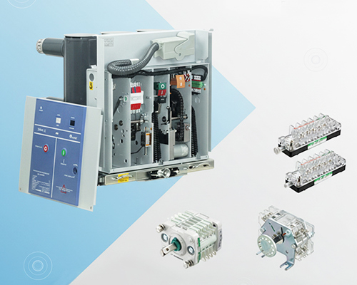
Signal Input – Accurate Feedback of VCB Main Contact Status: The auxiliary switch is mounted on the VCB’s main shaft, mechanically linked to the main contacts, allowing it to accurately reflect the closed or open position. The Normally Open (a-contact) and Normally Closed (b-contact) signals it provides are the sole basis for the secondary control system to determine the VCB’s actual status. This signal provides the most fundamental and accurate “position information” for triggering the anti-pumping logic.
Logic Determination – Conditions and Basis for Anti-Pumping Relay in VCB: When the VCB is detected in the closed position and a persistent closing command exists, the anti-pumping circuit is activated. At this moment, the accurate position signal provided by the auxiliary switch becomes the critical basis for triggering the anti-pumping mechanism.
Action Output – Instantaneous Interruption of the Closing Coil Circuit: Once the anti-pumping function is confirmed for activation, the auxiliary switch cooperates with the anti-pumping relay and other components to rapidly cut off the power supply to the closing coil. This action fundamentally prevents the circuit breaker from receiving another closing command in a short period, thus avoiding the “pumping” phenomenon.
Overall Benefits and Intelligent Development Trends
The auxiliary switch is an indispensable core component for implementing the anti-pumping function in medium and high voltage vacuum circuit breakers. By precisely controlling the energization and de-energization of the closing circuit, it effectively enhances VCB operational safety, significantly reduces the risk of equipment damage caused by misoperation, and improves the overall stability of the power system.
Looking ahead, facing the demands of smart grids and the Internet of Things (IoT) for high precision and fast response, the value of auxiliary switches is expected to deepen further. Their development direction is moving beyond traditional mechanical contacts and is likely to advance toward higher sensitivity, stronger environmental endurance, and deeper intelligent integration. By integrating advanced sensing and processing technologies, the auxiliary switch is expected to be upgraded to a smart terminal, achieving precise real-time monitoring of breaker status and enabling rapid response for anti-pumping interlocks. This will fundamentally enhance the efficiency and system-level reliability of the anti-pumping circuit within substation automation systems, providing robust technical support for the safe operation of the power grid.