Medium and high-voltage vacuum circuit breakers are crucial equipment in power systems for control and protection. Their core function is to reliably open and close circuits and to quickly interrupt fault currents in order to prevent equipment damage and ensure grid stability. However, a circuit breaker’s reliable operation doesn’t solely depend on its powerful main contacts; it also relies on an equally critical component—the auxiliary switch. This part acts as the breaker’s signal center, precisely transmitting the main contacts’ status to the control system to ensure every operation is accurate. Therefore, the correct selection and application of auxiliary switches are key to guaranteeing the control precision and operational safety of the entire power system.
The core function of an auxiliary switch is to provide reliable electrical signals by synchronizing its action with the opening and closing of the main contacts. Through its normally open (NO) and normally closed (NC) contacts, it sends accurate switch status information to control, signal, interlocking, and protection circuits. If the auxiliary switch’s action is out of sync with the main switch, or if its electrical performance is unstable, it could lead to minor issues like incorrect operations or control failures, or even serious safety accidents that threaten grid stability. Therefore, choosing high-quality, high-performance auxiliary switches is crucial.
Common Auxiliary Switch Types for Selection
Selecting an auxiliary switch is not a simple mechanical matching task, but a complex decision that requires comprehensive consideration of multiple factors. We need to fully evaluate its functions, electrical parameters, brand reputation, and product quality to ensure its performance and reliability. To precisely match different operational and application needs, auxiliary switches have evolved into various types. Below are several common types used in vacuum circuit breakers.
For a comprehensive selection process, we also offer detailed insights in “A Comprehensive Guide to Selecting Auxiliary Switches for Medium and High-Voltage Circuit Breakers“.
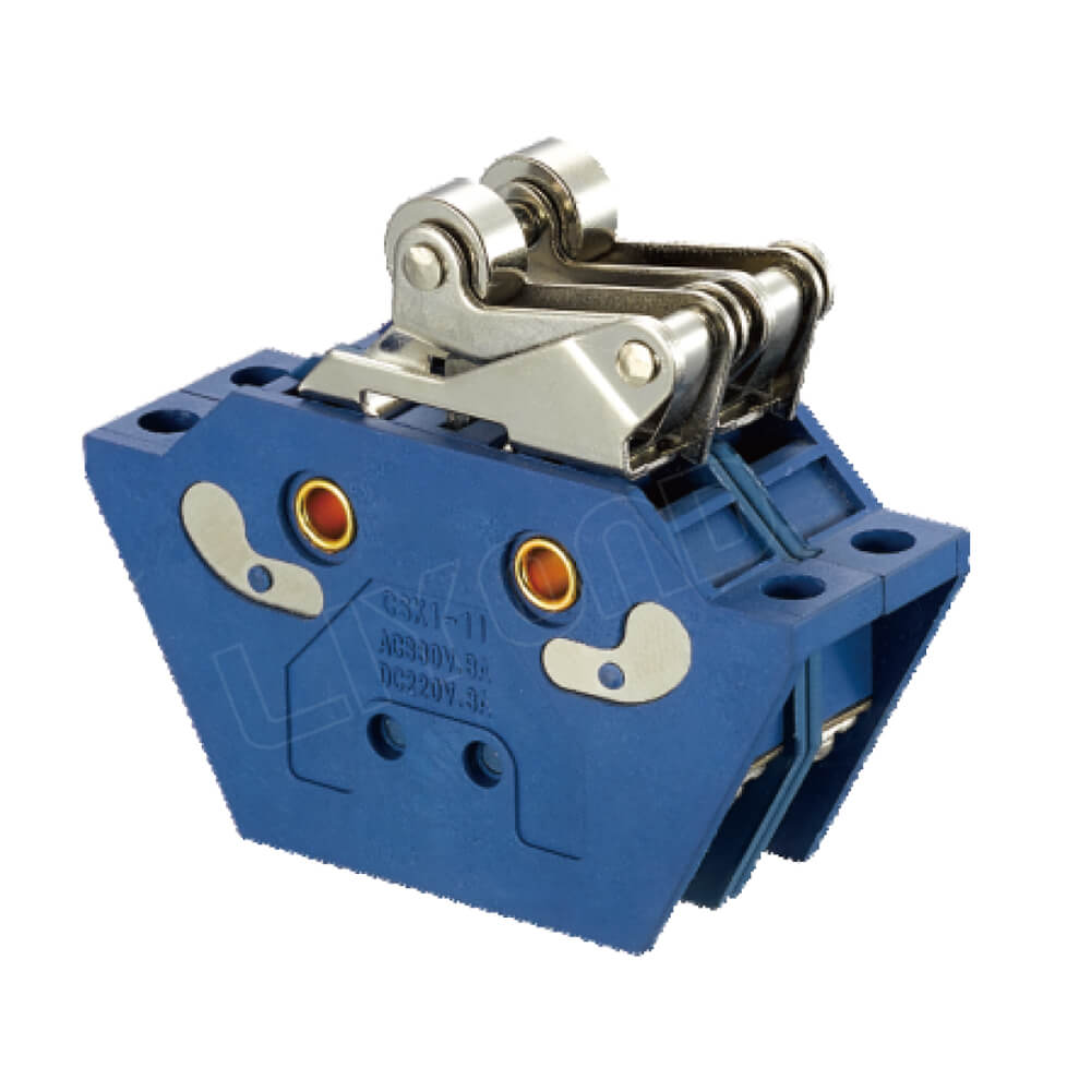
Magnetic Contactor Auxiliary Switch
-
Operating Principle: This type of auxiliary switch uses electromagnetic attraction to drive its contacts. When the control coil is energized, the generated magnetic field attracts the internal armature, causing the contacts to open or close. The core advantage of this switch is its high-capacity signal conversion capability. It can reliably convert weak control signals from PLCs and DCSs into high-capacity signals powerful enough to drive relays or contactors, effectively isolating and protecting the control circuit from electrical interference from the main circuit.
-
Selection Considerations:
-
Applicable Scenarios: This type of switch is mainly used in scenarios where weak control signals need to be converted to high-capacity signals, such as in remote or automated control systems. Its strong electrical isolation capability effectively avoids main circuit interference, ensuring the purity and stability of control signals. The CSK magnetic blow-out switch is a typical representative of this type. Its uniqueness lies in using magnetic blow-out arc suppression technology to enhance contact breaking capacity and service life, making it particularly suitable for industrial automation scenarios that require high-frequency, high-current signal conversion.
-
Electrical Parameter Matching: Pay attention to the rated voltage (typically DC24V,48V,110V or AC220V) and power of the coil to ensure a precise match with the control circuit’s electrical parameters. The choice of coil power directly affects its reliability; if it’s too low, it may not be able to pull in reliably, while if it’s too high, it will cause energy waste.
-
Operational Reliability: The focus is on its pull-in and release characteristics within the voltage fluctuation range, ensuring reliable operation even with unstable control voltage.
-
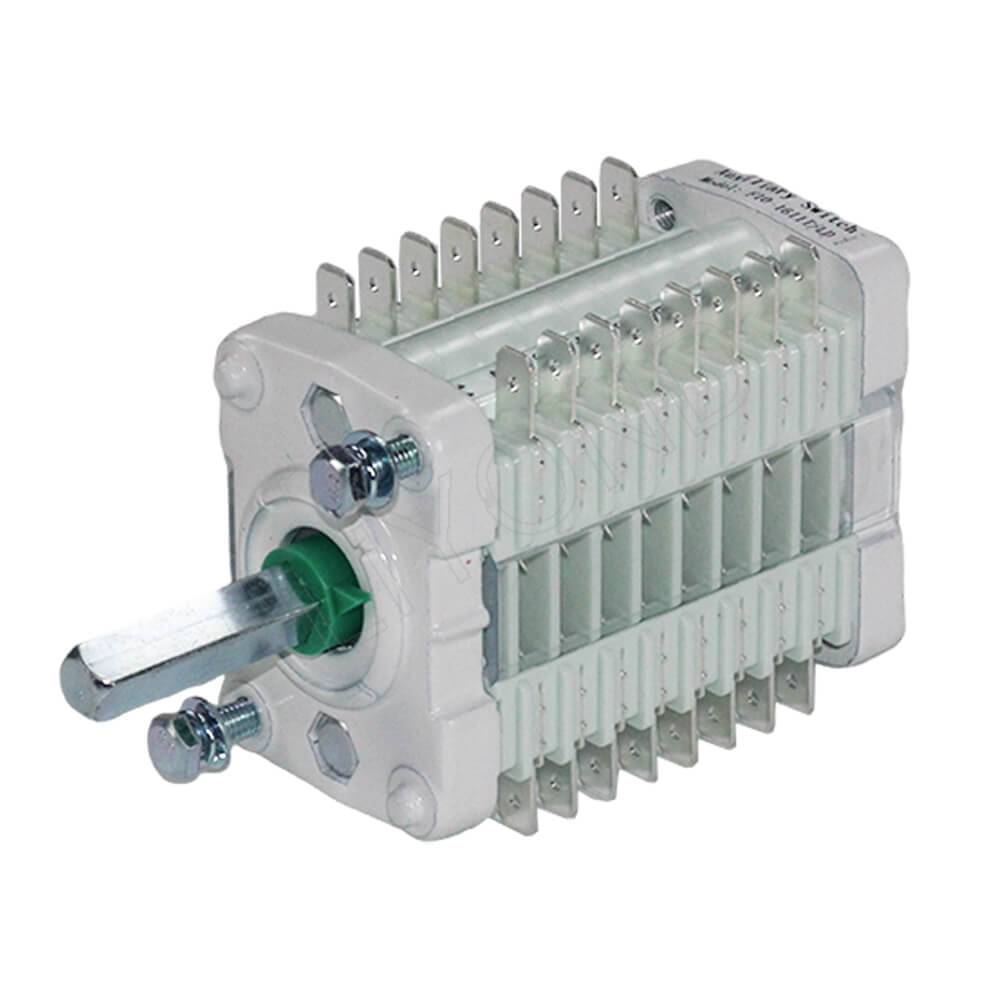
Position-Indicating Auxiliary Switch
-
Operating Principle: This is the most basic and common type of auxiliary switch. It is directly connected to the breaker’s opening and closing operating arm through a mechanical linkage. When the breaker operates, the auxiliary switch’s contacts switch accordingly, precisely reflecting the main contacts’ position status. Its internal mechanism usually consists of a cam or linkage system driving a contact set, ensuring every mechanical action is converted into a precise electrical signal.
-
Selection Considerations:
-
Core Function: Its main role is to provide the breaker’s real-time position information—whether it is “closed” or “open.” This is crucial for monitoring, interlocking, and protection circuits. For example, in “five-prevention” interlock logic (e.g., preventing the opening or closing of an isolating switch under load), the position-indicating auxiliary switch is an indispensable key component, and its action’s accuracy directly relates to operational safety. The F10, F6, FK10, and NK series are common models of this type. The F10, F6, and FK10 series are known for their high voltage resistance and multi-contact stacked design, which can meet complex interlocking and signal control needs, while the NK series, with its compact structure and excellent electrical performance, is widely used in vacuum contactors and other equipment.
-
Structure and Characteristics: When selecting, it is necessary to be clear about the number and type of contacts (NO/NC) and their switching sequence. For example, some applications require “make before break” or “break before make” interlock logic, which requires the auxiliary switch to have a specific contact switching sequence.
-
Mechanical Life and Durability: Since it synchronizes with the breaker’s operation, its mechanical life should match the breaker’s operating frequency. For high-frequency applications, a product with high mechanical durability and reliability must be chosen to avoid operational errors caused by contact failure.
-
.jpg)
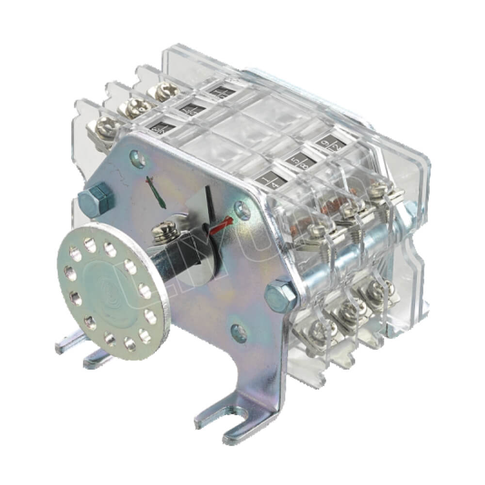
Current-Sensing Auxiliary Switch
-
Operating Principle: This type of switch has a built-in current sensor (such as a current transformer or a Hall sensor). It can real-time monitor the current flowing through the breaker’s main circuit. When the current value reaches or exceeds a preset threshold, it automatically triggers its internal contacts. Unlike traditional overcurrent protection, this switch is typically used for signal acquisition and auxiliary protection, providing a more flexible monitoring method.
-
Selection Considerations:
-
Core Function: It is an important component for implementing overcurrent warnings and load monitoring. In some non-primary protection scenarios, it serves as supplementary protection, providing additional security if the main protection fails. Furthermore, by continuously monitoring the load current, it can also be used for equipment status monitoring, assisting in preventative maintenance.
-
Sensor Type Selection:
-
Current Transformer (CT) Type: Suitable for high-current scenarios, it offers high reliability and good electrical isolation, but it can usually only monitor AC current.
-
Hall Sensor Type: It can monitor both AC and DC currents and has a fast response speed, making it suitable for scenarios with high requirements for transient current changes.
-
-
Selection Factors: The appropriate current transformer ratio or sensor range should be selected based on the circuit’s maximum normal current and short-circuit current, and its response time must meet protection requirements. For example, for scenarios requiring a millisecond-level response, a faster Hall sensor should be chosen.
-
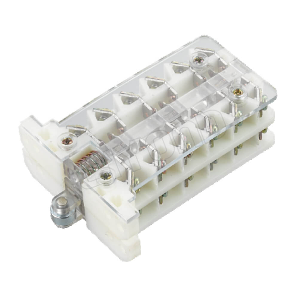
Temperature-Sensing Auxiliary Switch
-
Operating Principle: This type of switch has a built-in temperature sensor (such as a thermistor or a bimetallic strip), and its contacts change state with temperature changes. It is usually installed in areas that are prone to heating, such as the main contact connections, arc chambers, or around the coils of the circuit breaker, to provide real-time temperature monitoring.
-
Selection Considerations:
-
Core Function: Its main role is overheat protection. When a circuit breaker’s temperature rises abnormally due to poor contact, overload, or poor heat dissipation, it can promptly send a warning or trip signal, effectively preventing equipment from being damaged by overheating.
-
Application Scenarios: It is particularly suitable for circuit breakers operating under heavy loads for extended periods and in environments with high demands for equipment thermal stability. It can effectively identify potential contact failure points, providing an important basis for preventative maintenance.
-
Sensor Type Selection:
-
Bimetallic Strip Type: Simple in structure and low in cost, it is usually used to provide a trip signal at a fixed temperature point (e.g., 70∘C,80∘C).
-
Thermistor/Thermocouple Type: It offers higher precision and can achieve continuous temperature monitoring, transmitting an analog signal to the control system for more detailed temperature curve analysis.
-
-
Selection Factors: A model with a suitable trigger temperature should be chosen, and its installation location must accurately reflect the thermal state of the monitored point. At the same time, the sensor’s response speed should be considered to ensure timely action when the temperature rises sharply.
-
Common Application Scenarios for VCB Auxiliary Switches
Auxiliary switches play a key role in various application scenarios. They are at the core of automation, safety interlocking, and status monitoring. Different types of switches perform unique and indispensable functions in their respective environments.
-
High-Voltage Substations: In substations, where reliability is highly demanded, circuit breakers require precise feedback on their open/closed status. In this case, the F10 series auxiliary switch, with its multi-contact and high reliability features, is often used in the main circuit breaker to provide accurate position signals to the central control system and remote monitoring system. At the same time, to ensure equipment safety, the FK10 series is also used in the breaker’s operating circuit to achieve more complex interlocking logic.
-
Industrial Automation and Motor Control: In industrial scenarios like steel and chemical plants that require frequent starting and stopping of heavy-duty motors, vacuum contactors are core equipment. The NK series auxiliary switch, with its compact size and excellent electrical performance, is often used in these devices to achieve synchronized control and position interlocking with the motors. If a weak PLC signal needs to be converted into a high-power driving signal to control a contactor, the CSK series magnetic contactor switch is the ideal choice.
-
Wind Power and New Energy Sector: Circuit breakers in wind turbines are usually in an unattended or remotely monitored state. In addition to conventional position feedback, overcurrent and overheat warnings are extremely important. In this case, equipping the breaker with both current-sensing and temperature-sensing auxiliary switches can achieve real-time monitoring of the equipment status. Once an abnormality is found, it can immediately send a warning signal, which can be handled through the remote control system, greatly improving the equipment’s operational safety and maintenance efficiency.
Auxiliary Switch Installation and Maintenance Guide
Correct installation and regular maintenance are critical to ensuring the long-term reliable operation of auxiliary switches. Improper installation can lead to poor contact synchronization, accelerated mechanical wear, and even failure.
-
Installation Steps:
-
Mechanical Alignment: Ensure that the auxiliary switch’s transmission mechanism is strictly aligned with the breaker’s opening and closing operating arm to avoid off-center or jamming issues.
-
Secure Fastening: Use a torque wrench to tighten the installation bolts to the specified torque. This is to ensure a secure fit and also to prevent over-tightening which can cause the housing to deform or damage the internal mechanism.
-
Electrical Wiring: Strictly follow the wiring diagram for electrical connections. Check the contact types (NO/NC) and wiring sequence to prevent control circuit logic from being confused due to incorrect wiring.
-
-
Routine Maintenance:
-
Regular Checks: Check whether the auxiliary switch’s fastening is loose and whether the transmission mechanism is flexible.
-
Cleaning and Maintenance: Regularly clean dust and dirt from the housing and terminals to ensure good insulation performance.
-
Functionality Test: During circuit breaker maintenance, you can also test whether the auxiliary switch’s opening and closing actions are synchronized with the main contacts and use a multimeter to check whether the contact’s on/off status is normal.
-
Conclusion
In summary, choosing the right auxiliary switch for a medium and high-voltage vacuum circuit breaker is not a matter of a single indicator, but requires a comprehensive consideration of its operating principle, functional characteristics, and actual application environment. The magnetic contactor type provides powerful signal conversion, the position-indicating type is for basic status feedback, the current-sensing type is responsible for overload protection, and the temperature-sensing type focuses on thermal status monitoring. Only by deeply understanding and precisely matching the characteristics of these different types of auxiliary switches, and by supplementing them with correct installation and maintenance, can the reliability of the control system be ensured, ultimately guaranteeing the safe and stable operation of the entire power system.