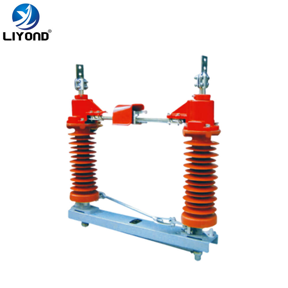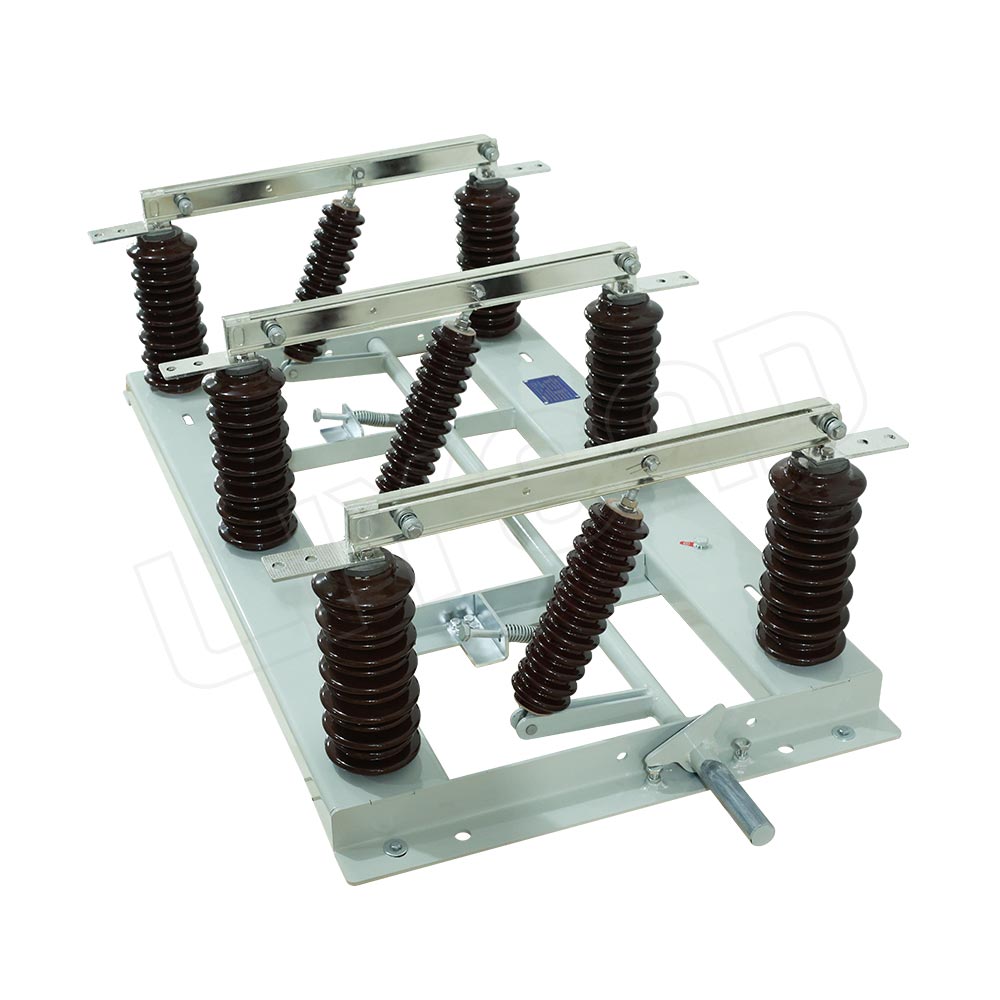
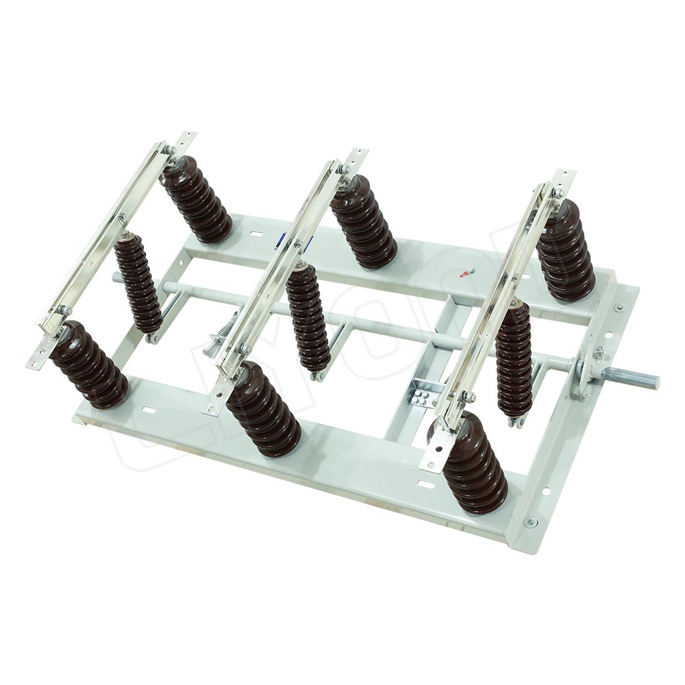
The isolating switch is composed of three identical single-pole isolating switches. When installing, the three poles are formed as a whole by the pipe connecting rod, and the CS8-1 manual operating mechanism is used. Each single-pole isolating switch has a separate iron frame, and two post insulators are installed at both ends, which are equipped with contacts. There is a rotating shaft in the middle of the iron frame, and the knife switch is opened and closed by means of a pull rod insulator. The GW1 switch is a double-column outdoor high-voltage isolation switch composed of three single poles. The switch is a one-way opening type. It consists of a base, an insulator, a contact knife guide and a conductive part. On both sides of the base, there are tie-rod insulators, a crank arm and a rotating shaft in the middle to open or close the switch. The switch can be equipped with an anti-theft operating mechanism or a common operating mechanism.
Technical parameters of the isolating switch
|
No.
|
Item
|
Unit
|
Data
|
||||
|
1
|
Rated voltage
|
kV
|
12/24/40.5
|
||||
|
2
|
Rated current
|
A
|
630/1000/1250
|
||||
|
3
|
Rated power frequency
|
Hz
|
50/60
|
||||
|
4
|
Rated peak withstand current
|
kA
|
50/63
|
||||
|
5
|
Rated short-time withstand current
|
kA
|
20/25
|
||||
|
6
|
Rated short-time withstand current duration
|
s
|
4
|
||||
|
7
|
Main loop resistance
|
μΩ
|
12kV≤80
|
24kV≤90
|
40.5kV≤100
|
||
|
8
|
1min(dry)power frequency withstand voltage
|
phase to phase
phase to earth
across open contacts
|
kV
|
42/48
|
50/60
|
95/115
|
|
|
9
|
1min(wet)power frequency withstand voltage
|
34
|
50
|
85
|
|||
|
10
|
Lightning impulse wuthstand voltage(peak)
|
75/85
|
125/145
|
185/215
|
|||
|
11
|
Mechanical life
|
Times
|
2000
|
||||
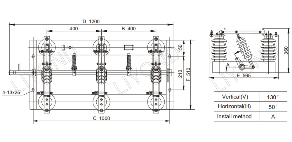
Dimensional drawing reference