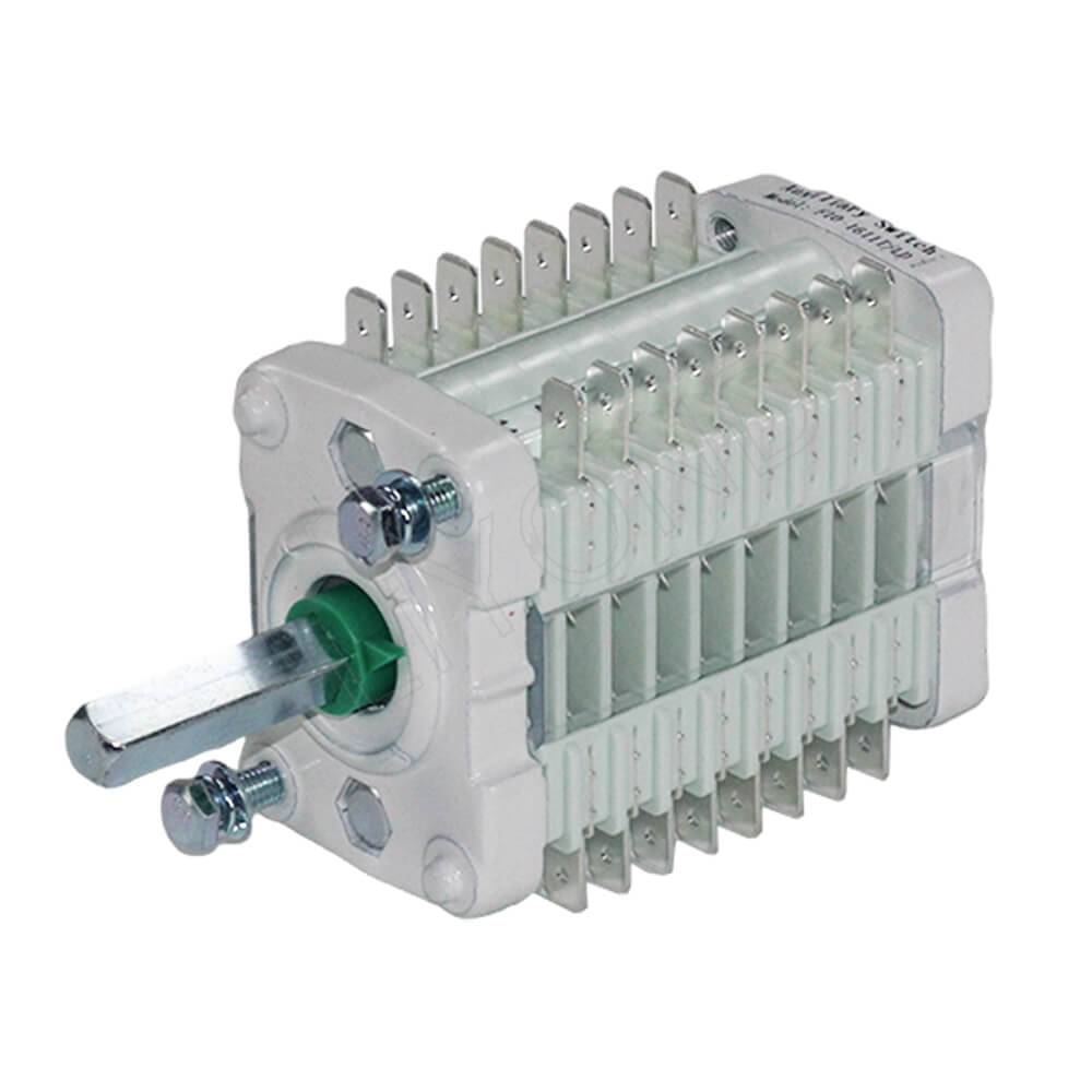
Auxiliary Switches' Essential Signal Interface in MV Switchgear
Medium-voltage (MV) switchgear is a cornerstone of modern power distribution systems, with its primary function being the precise control and safe isolation of the main power circuit. Within this complex electrical apparatus, the auxiliary switch plays a critical role. It is a vital signal-conversion component that accurately translates the mechanical state of primary devices, such as circuit breakers, disconnectors, and earthing switches, into electrical signals. These signals are the foundational building blocks for the secondary control circuits, interlocking protection, and Supervisory Control and Data Acquisition (SCADA) systems, all of which are essential for ensuring the safe, reliable, and efficient operation of the entire power grid. Though small in size, the auxiliary switch acts as a crucial bridge connecting the physical state of the main circuit with the intelligent control system.
Functional Applications of Auxiliary Switches in MV Switchgear
Auxiliary switches are used in a wide range of applications. Depending on the primary equipment they are attached to and the functional requirements, they can perform several key tasks.
1. State Signal Indication and Feedback
The most fundamental function of an auxiliary switch is to provide real-time status feedback of the equipment. It uses the opening and closing of its contacts to accurately reflect the physical position of the primary device. For instance:
-
Circuit Breaker Status: When a circuit breaker is closed, normally open (NO) contacts of the auxiliary switch in circuit breaker will close, sending a “closed” signal to the control circuit. Conversely, when the breaker is open, the normally closed (NC) contacts close, signaling an “open” status. These signals are used to illuminate indicator lights on the control panel or to provide graphical status updates on a remote monitoring interface, giving operators a clear and immediate view of the equipment’s state.
-
Withdrawable Unit Position: In withdrawable switchgear, auxiliary switches indicate the position of the mobile unit. For example, when the unit is racked into the service or test position, the auxiliary switch provides a corresponding “service position” or “test position” signal, ensuring the correctness of the operation.
-
Earthing Switch Status: Auxiliary contacts on the earth switch in switchgear indicate whether the earthing blades are in a closed or open position. This is a crucial component for executing key “five-prevention” interlocks.
2. Electrical Interlocking Control
Auxiliary switches are central to implementing the “five-prevention” interlocking logic in substations. This system is designed to prevent a series of common human errors (e.g., preventing a load-bearing switch from being closed, or preventing a live circuit from being earthed) that could lead to equipment damage or personnel injury. For example, a FK10 auxiliary contact switch can be used to enforce a specific sequence of safe operations and prevent a load-bearing switch from being closed, which is a common cause of accidents. Through precise contact logic, the auxiliary switch enforces a specific sequence of safe operations.
-
Preventing Disconnector Operation Under Load: When the circuit breaker is in the closed position, its auxiliary switch interrupts the power supply to the operating circuit of the disconnector. This physically prevents the dangerous and incorrect operation of opening or closing the disconnector under load.
-
Preventing Energized Earthing: When the earthing switch is in the closed position, its auxiliary switch cuts off the closing circuit for the circuit breaker. This means that no closing operation can be performed on the circuit breaker unless the earthing switch is fully opened, ensuring absolute safety during maintenance.
3. Remote Control and Automation
In modern smart substations, the status signals provided by auxiliary switches are the foundation for remote control and automated operations. These signals are collected by the SCADA system or Substation Automation System (SAS).
-
Remote Status Monitoring: Operators can monitor the real-time operational status of all components within the switchgear from a remote control center via the SCADA system, eliminating the need for on-site checks and significantly improving operational efficiency.
-
Remote Operation Execution: Based on the interlocking signals provided by the auxiliary switches, the system can determine if the conditions for a remote close or open command are met. The system will only execute the command if all safety conditions are satisfied, ensuring that remote operations have the same level of safety as local ones.
-
Fault Diagnosis and Analysis: The signals from auxiliary switches also serve as inputs for fault recording and event logs, helping maintenance personnel quickly pinpoint issues and perform accurate fault analysis when a problem occurs.
Selection and Integration of Auxiliary Switches
The selection of the right auxiliary switch is of paramount importance during the design and manufacturing of MV switchgear. MV switchgear manufacturers understand that the quality of these components directly impacts the overall reliability of the final product. Several technical factors must be considered:
-
Mechanical Endurance: The contacts of the auxiliary switch must be able to withstand a high frequency of operations. Its mechanical life directly impacts the long-term reliability of the switchgear.
-
Electrical Performance: The rated voltage, current, and breaking capacity of the contacts must meet the electrical requirements of the secondary circuit to ensure accurate signal transmission.
-
Environmental Adaptability: It is essential to select products that can operate reliably within the demanding environment inside the switchgear (e.g., high temperature, humidity, and vibration).
In terms of system integration, the installation location and wiring of the auxiliary switch must strictly adhere to design specifications to ensure synchronization with the primary equipment’s movements and the accuracy of signal transmission. The wiring of its signal circuits should also be designed with electromagnetic interference (EMI) immunity in mind to prevent false signals that could compromise the entire system’s safety logic.
.jpg)
Conclusion: A Cornerstone for Switchgear Reliability
In conclusion, the auxiliary switch is an indispensable and powerful component in medium-voltage switchgear. It ensures a seamless connection between the mechanical state of primary devices and the electrical control system of the secondary circuit through reliable signal conversion. This enables complex interlocking protection, efficient automation, and precise remote monitoring. Despite its relatively small size, its role is critical to the operational safety of the switchgear and the stability of the power grid. Therefore, the quality, selection, and integration of auxiliary switches should be given the highest priority in the design, manufacturing, and maintenance of all switchgear.