Every electrical power distribution system must have protective devices that safeguard appliances and equipment from unfortunate occurrences. Among these protective devices are earth switches, which are connected to components of switchgear for keeping electrical equipment safe and preventing further harm, such as fire outbreak or injury to users.
An earth switch is a mechanical switching device for protecting parts of a circuit. It is capable of sustaining currents for a specific time under abnormal conditions such as short circuits. During normal circuit conditions, it doesn’t carry any current. It’s only called into action when there is an abnormal condition. An earth switch is a must-have in every electrical installation as it protects the technicians and switchgear during abnormal current conditions.
In this post, we will further explain what is an earthing switch in switchgear, and we will discuss everything you need to know about the protective device.
What is an Earthing Switch
An earthing switch is also known as a grounding switch. Earthing switch and grounding switch are used interchangeably. It’s a protective device that’s included in switchgear components like circuit breakers and isolators. When circuit breakers are removed and racked out, earthing switches automatically ground the part of the bus bar adjacent to the circuit breakers. For isolators, the earthing switches make contact with the bus bar when the isolator isolates the circuits, discharging any charges that may have gathered there.
An earth switch in switchgear is used to ground the remaining change in a power line after the power line has been removed from its source. A residual charge always remains in the circuit after it has been severed or opened by the circuit breaker and isolator. An earthing switch is usually used to discharge the charge.
Earthing switches have a snap action closing mechanism. They protect technicians and staff when there is an abnormal current. They are designed to withstand short circuits; they can also be motorized. Examples are the high voltage earthing switch and the high speed grounding switch. An earth switch in a substation has the ability to create short circuits in order to safeguard other electrical devices from damage. It’s used with several high-voltage switchgear and it also serve as a protective device in the overhaul of high-voltage electrical equipment.
Earthing switches, circuit breakers, and isolators are all connected in the ring main unit switchgear (RMU). If there is a need for the circuit to be opened or broken for maintenance or any other reason, the right sequence for the operation of these three devices (earthing switches, circuit breakers, and isolators) must be followed. If the right steps are not followed, you won’t just be causing damage to your circuit and equipment, but you will also be putting yourself in danger. To perfectly house these components, you can contact Elecspare, one of the gis switchgear manufacturers for a reliable insulating medium for your devices.
Earthing switches and isolating switches are often combined into a single device. In this case, in addition to the main contact, the isolating switch also has an earthing switch for grounding one end of the isolating switch after opening. The main contacts and the earthing switch are usually mechanically interlocked in such a way that the earthing switch cannot be closed when the isolating switch is closed, and the main contacts cannot be closed when the earthing switch is closed.
The grounding switch can be divided into two types: open type and closed type. The conduction system of the former is exposed to the grounding switch similar to the disconnector in the atmosphere, and the conduction system of the latter is enclosed in the charging SF. or insulating medium, such as oil.
Earth switch in switchgear closes short-circuit current and has certain short-circuit making ability and dynamic and thermal stability. It doesn’t have an arc quenching device as it does not need to break the load current and short-circuit current. The lower end of the blade is usually connected to the grounding point through a current transformer. Current transformers can give signals for relay protection.
Earthing switches have several structures. We have the single-pole, the double-pole, and the three-pole earthing switches. The single-pole is only used when you’re dealing with the neutral point grounding system. The double-pole and three-pole structures are used for the neutral point ungrounded system, and share an operating mechanism for operation.
Earthing Switch in Low-voltage Systems
The fundamental purpose for the design of grounding switches in low-voltage systems, which deliver electric power to the broadest class of end-users, is the safety of customers who use electric products and their protection against electric shocks.
The grounding system, in conjunction with other switchgear protection components like load break switch and residual current devices, ensures that a person does not touch a metallic object whose potential relative to the person’s potential exceeds a safe threshold, which is normally set at 50 volts.
From the safety point of view, an earthing switch is also necessary for low-voltage electricity networks with a phase to neutral voltage exceeding 240 to 690 volts, which is typically utilized in industries, mining equipment, and machinery rather than publicly accessible networks.
Earthing Switch in High-voltage Systems
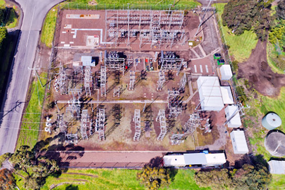
The focus of an earth switch in substation, which is significantly less accessible to the general public, does not prioritize safety as it does in the low-voltage system. Rather, it focuses more on supply dependability, protection reliability, and impact on equipment in the event of a short circuit. Because the current channel is mostly blocked through the earth, only the amplitude of phase-to-ground short circuits, which are the most prevalent, is considerably affected by the choice of earthing system.
What is Earthing Switch Used for
- Earthing switch is used to provide a ground line to an underground or delta-connected system.
- Earthing switch allows the connection of phase-to-phase loads.
- The earthing switch in substation is grounded to give a low-impedance link to the ground, which keeps the system neutral.
- The earthing switch in switchgear ensures that the magnitude of transient overvoltage is limited during a re-striking ground fault.
- When there are line-to-ground problems, a ground fault current source is provided by an earthing switch.
- It is used to ground electrical devices to meet the protection requirement.
What is the Function of Earthing Switch
- An earth switch in switchgear primary’s function is to protect technicians and switchgear from an inadvertent operation. It can be reliably closed against short-circuit currents.
- It is connected to circuit breakers, and when they are cleared and racked out, the bus bar that is adjacent to the circuit breakers is grounded through earthing switches automatically. This process protects technicians, maintenance personnel, and users from any unfortunate accidental voltages.
- It is used for static electricity and electromagnetic induction current. In two or more overhead transmission lines with the same tower or adjacent parallel arrangement, when one or several lines are out of power, due to the electromagnetic induction and electrostatic induction between it and the adjacent live lines, the outage circuit will generate induced voltage and induced current. Hence, the grounding switches for this type of line.
- It’s used to close short-circuit current. An earthing switch with a rated short-circuit making current shall be able to close at any applied voltage including its rated voltage and any current including its rated short-circuit making current. The earthing switch has a rated short-circuit making the current equal to the rated peak withstand current.
- An earthing switch in a substation performs cogent functions in a big or heavy-duty power transformer as it allows the electrical grid to have a consistent point of reference for voltage. Otherwise, voltages may vary from one place to another. It guarantees safety for both the transformer and people to use power.
Types of Earthing Switch
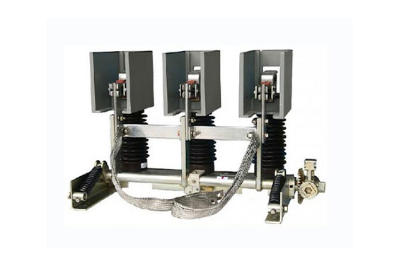
1. Indoor high voltage grounding switch
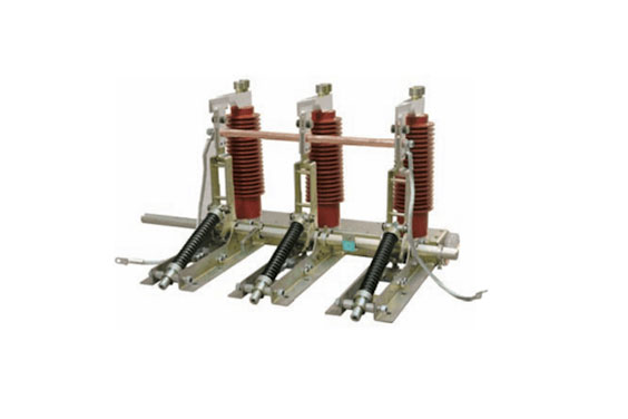
It is suitable for indoor 3-12kV three-phase AC 50(60) Hz power systems to be used in conjunction with various types of high-voltage switch cabinets. It can also be used as grounding for high-voltage electrical equipment maintenance. The main structure, the grounding switch, is composed of a bracket, a grounding knife assembly, a static contact, a sensor, a shaft, an arm, a compression spring, a conductive sleeve, and a soft connection.
When the operating mechanism is operated to close the grounding switch, it acts as a torque to make the main shaft overcome the resistance torque. Drive the crank arm to rotate in the closing direction, and make the operating lever on the grounding knife pass through the dead point of the compression spring, and the compression spring releases energy. Make the earthing switch close quickly in the closed position. The grounding knife on the grounding knife assembly is in a firm and reliable contact with the flange portion (knife edge) of the static contact through the disc spring.
When the torque is applied, the main shaft overcomes the main torque and the spring force drives the arm to rotate in the direction of opening, and makes the grounding knife pressure spring pass through.
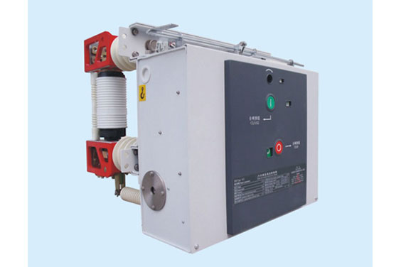
2. Indoor high voltage electric grounding switch
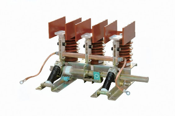
An indoor high voltage electric grounding switch consists of a motor, a driving device, an electric air control device, as well as the main shaft of the grounding switch.
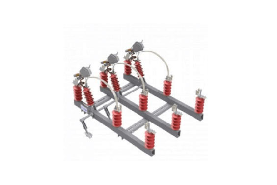
3. FES Fast Earthing Switch
According to the different requirements of the installation location, the earthing switch is divided into two types: the earthing switch for maintenance (ES) and the earthing switch for fault fast closing earthing switch(FES).
The FES fast earthing switch (FES) has the ability to close short-circuit current, and open and close induced current, so it is an important protection device during maintenance. It’s also operated by an electric spring mechanism. The fault earthing switch is suitable for the grounding switch on the outside of the line. The mechanism operation is generally installed on the line side of the line outlet disconnector, and is electrically interlocked with the related disconnectors and circuit breakers.
While the earthing switch is used to ground or disconnect. When the equipment is overhauled, an obvious grounding point should be formed on all sides where incoming electricity may be generated. It mainly includes busbar grounding switches, ground switches for outgoing and incoming lines (installed on the busbar side and outgoing side of the main transformer circuit breaker, and on the busbar side of the circuit breaker).
What is Earthing Switch Symbol

The earthing switch is mainly composed of a bracket, a grounding knife assembly, a static contact, a sensor, a shaft, an arm, a compression spring, a conductive sleeve, and a soft connection.
When the earthing switch is closed by manual operation, the acting torque causes the main shaft to overcome the torque, drive the arm to rotate in the direction of closing, and make the grounding knife pass through the coil spring and the flange to the static contact. The parts (knife edge) are firmly in contact with each other.
When the manual opening is operated, the acting force makes the main shaft overcome the torque and spring force, drives the arm to rotate in the direction of splitting, and makes the grounding knife pressure spring pass through the dead point, and the egg-pressing energy storage ends for the next closing.
What is a High Speed Grounding Switch (HSGS)
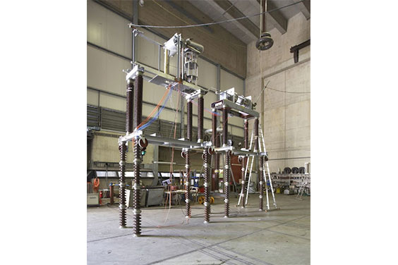
The high speed grounding switch is also known as the high speed earthing switch. Also, sometimes it is called a fast earthing switch. It is a fast isolating switch with the ability to close short-circuit current and is specially used for artificial grounding of the power system. It is generally equipped with a hydraulic or electric quick-acting mechanism.
In a power system with multiple parallel main transformer branches, in order to save investment, the high-voltage circuit breaker of the main transformer branch is usually replaced by a fast grounding switch. When the main transformer body fails, the main transformer protection starts the fast grounding switch on the high-voltage side for closing operation. This causes the power system to be grounded manually, and starts the relay protection device of the power system, causing the circuit breaker on the opposite side of the transmission line to open, and cutting off the fault of the main transformer.
The quick earthing switch is usually also installed in gas-insulated metal-enclosed electrical appliances and is installed on the outer part of each outlet line to close the induced current generated by the parallel circuit.
The fast grounding switch has the ability to close short-circuit current, usually 80 kA in 110kV power systems and 125kA in 220kV systems. The quick grounding switch in gas-insulated metal-enclosed electrical appliances is sealed in an SF6 gas-insulated cylinder, and the requirement for closing short-circuit currents are relatively easy to achieve. The open-type high speed grounding switch is often replaced by a vacuum circuit breaker when the short-circuit current required to be closed is large.
Design of High Speed Grounding Switch
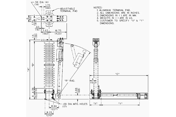
The High Speed Grounding Switch (HSGS) is installed at the outlet end of the Gas Insulated Switchgear (GIS), and it is operated by a spring mechanism. It performs a secondary role of safeguarding the power system when an accident happens. HSGS may be accidentally energized and closed during operation or maintenance, resulting in artificial ground faults. In order to prevent the accident from expanding, ensure that the HSGS has the specified short-circuit making capacity.
When the ground fault is closed, the short-circuit current flows from 2 to 1, the three-phase moving contacts are kept insulated between phases through the insulating plate 3, and the fault current is introduced to the ground through 4. Make sure that the HSGS that has been in the grounding closed state also has the ability to withstand short-term current.
When the HSGS fails to close, go through these two processes to remedy the close failure:
- Firstly, the insertion force on the HSGS moving contact of the operating mechanism should be greater than the contact spring reaction force of the static contact and the electric repulsion of the contact when it is just in contact. This ascertains that the moving contact can be inserted into the static contact.
- Secondly, after insertion, the kinetic energy of the HSGS moving contact system should be sufficient to overcome the resistance work done by the contact friction force of the contact spring and the electric friction force during the overtravel, so as to ensure that the moving contacts are closed in place.
Difference between Earthing Switch and High Speed Grounding Switch
The earthing switch is arranged next to the disconnector on both sides of the circuit breaker, and only plays the role of grounding on both sides of the circuit breaker during maintenance. The high speed grounding switch, on the other hand, is arranged on the line side of the outgoing disconnector of the outgoing circuit, which has two functions:
- Opening and closing parallel overhead lines generate inductive current due to capacitive current and electromagnetic induction generated by electrostatic induction.
- The fast grounding switch will quickly ground the main circuit, and use the circuit breaker to cut off the fault current when the insulator inside the casing has a creepage phenomenon or an arc inside the casing.
The function of the fast earthing switch should be on the outside of the line switch. When a single-phase fault occurs in the line, the switches on both sides of the faulty line are disconnected. However, due to the electromagnetic coupling between the normal phase and the fault-receiving phase, the normal phase provides the potential for the faulty phase. Supply current does not use the fault point to dissociate, the arc extinguishing time will be extended, or even the arc will not be extinguished.
In order to reduce the submerged supply current, when the switches on both sides are disconnected, the automatic device action immediately closes the fast grounding switches on both sides. A set arc extinguishing time, then disconnecting the fast grounding switch, and then single-phase reclosing, can improve the success rate of closing.
Relationship between Circuit Breaker and High Speed Grounding Switch
The relationship between circuit breaker and fast earthing switch (HSGS) can be viewed from two aspects. Firstly, it can be viewed from the aspect of switch tripping, and secondly, it can be viewed from the aspect of reclosing.
1. In terms of switch tripping, it is actually simple. When a single-phase fault occurs in the line, the switches on both sides of the faulty line are disconnected. However, due to the electromagnetic coupling between the normal phase and the faulty phase, a submerged supply current occurs, which is not conducive to arc extinguishing.
In order to reduce the submerged supply current, when the switches on both sides are disconnected, the automatic device action immediately closes the HSGS on both sides to achieve the effect of rapid arc extinguishing.
2. The biggest use of HSGS is to connect with the switch to realize reclosing. These are the steps to follow to do this:
- A single-phase-to-ground short-circuit fault occurs, resulting in an arc.
- The switches at both ends of the faulted phase trip (primary arc) are extinguished, and the submerged arc (secondary arc) is generated.
- The HSGS installed in the faulty phase is grounded, and the submerged arc is extinguished.
- The HSGS is disconnected.
- The reclosing action switch is reclosed.
Conclusion
Earthing switches, also called grounding switches, are protective devices that ensure that technicians and switchgear are safe from inadvertent operations. They are used together with switchgear components like isolators and circuit breakers to make sure that no accident happens as a result of abnormal current in the electrical system.
In this post, we’ve discussed everything you need to know about an earthing switch in switchgear starting from what it means, what it is used for, its functions, types, symbols, and so much more.
For further inquiries, contact Elecspare, a professional switchgear manufacturer who makes reliable protective electrical components, including earthing switches that ensure the safety of technicians, users, and switchgear from accidents.