The 21st century is technologically and electronically advanced. We have become so accustomed to the conveniences of technological advancements that this generation would most probably be unable to envision life without electricity and the internet.
The flow of electrical power or charge is described as electricity. But the transmission of electrical power is not flawless. Electricity, like any other invention, has flaws. Minor fluctuations in the power supply may occasionally happen, causing harm to the machinery.
Medium voltage switchgear is a rudimentary device specifically built to stabilize any uneven or irregular flow of electricity, and they are used to minimize potential damages during unexpected circumstances.
Scroll down to learn more about medium voltage electric switchgear, the MV switchgear components, and where to get the best ones.
What Is Medium Voltage Switchgear?
Medium-voltage switchgear refers to switchgear systems that can sustain voltages between 3 and 36 kV. There are several varieties of medium voltage switchgear, including:
- Metal-enclosed outdoor type
- Metal-enclosed indoor type
- Outdoor style without metal enclosure and a variety of other variations
Regardless of the type of circuit blocker employed, the primary purpose of the medium switchgear is to interrupt the current once a fault occurs. Insulating oil, SF6 gas, or vacuum can be used as an interruption medium in medium voltage switchgear.
The following are the essential functions that medium voltage switchgear can perform:
- Switching on and off usually.
- Short circuit current interruption.
- Switching of capacitive currents.
- Switching of inductive currents.
- Other various applications
The operations above should be carried out safely.
What Are MV Switchgear Symbols?
Manufacturers use switchgear symbols to demonstrate the design of the switch gear. The preliminary design is developed using these symbols, and the equipment is subsequently produced without flaws and delivers flawless service.
Wires, disconnectors, fuses, arrestors, resistors, and transistors are some of the electrical and electronic devices or functions represented by switchgear symbols.
Medium Voltage Switchgear Design Guide
To design the medium voltage switchgear, there are a few concepts we have to go through. Here are some of the concepts necessary to understand and build a suitable working MV switchgear.
-
Voltage
Operating Voltage U (Kv)
The operating voltage U (kV) is the voltage on the circuit where the equipment is installed. It’s used on all of the equipment terminals.
Rated Voltage Ur (Kv)
Rated voltage Ur (kV) denotes the maximum voltage that the equipment can handle. This voltage value determines the insulation level.
The rated voltage is always higher than the working voltage.
Insulation Level UD and Up
Level of insulation refers to the dielectric resistance of equipment to power frequency overvoltage, aging, and lightning impulses.
Ud refers to the overvoltages that occur in the internal origin as a result of any circuit modifications such as opening or shutting a circuit, a breakdown, or a short across an insulator. The unit is kV r ms at 1 min.
It is determined in a laboratory by the rated power-frequency withstanding voltage for one minute.
Up refers to the overvoltages that occur outside as lightning falls on or near a line.
The resulting voltage wave is replicated in a laboratory and is the rated lightning impulse withstand voltage. The unit is kV at peak.
-
Current
Rated Normal Current: IR (A)
The rated normal current refers to the RMS value of current that equipment can handle when permanently closed without exceeding the temperature rise specified in regulations is referred to as Ir (A).
Rated Short-Time Withstand Current: Ik (A)
Ik (A) is the RMS value of the current that the switchgear can carry in the closed state for a specific interval of time. The brief period lasts between 1 and 3 seconds.
Rated Peak Withstand Current: Ip (A)
In the closed position, Ip (A) is the peak current linked with the first primary loop of the specified short-time withstand current that the switchgear can carry.
Operating Current: I (A)
The operating current is calculated using the total consumption of all connected devices. It is the current that passes through the equipment.
The operating current can be calculated by the power of the current provided by the consumers.
-
Frequency
In most cases, just two frequencies are used over the world:
- In Europe, the frequency is 50 Hz.
- In America, the frequency is 60 Hz.
-
Short Circuit Power
The short-circuit power is calculated based on the network configuration and the impedance of its components such as lines, cables, transformers, motors through which the short-circuit current flows.
It is the maximum current that the circuit can offer to an installation during a fault for a specific operating voltage. It is represented in MVA or kA r ms.
U Operating voltage (kV)
Isc Short-circuit current (kA r ms)
Minimal Short-Circuit Current:
Isc min = (kA r ms)
RMS Value of Maximal Short-Circuit Current:
Ith = (kA r ms) At 1 or 3s
The Peak Value of the Maximum Short-Circuit Current:
Idyn = (kA) at peak
-
Busbar Calculation
A group of conductors that receives power from entering feeders and transmits it to outgoing feeders is known as an electrical busbar. The MV isolator and circuit breaker constitute the busbar system. Yes, the same vacuum circuit breaker that we stated in the switchgear components.
When an error starts, the circuit breaker is tripped, and the faulty section of the busbar is isolated from the circuit, preserving the intact portion of the busbar.
The electrical bus is available in:
- Rectangle
- Cross-sectional
- Round and many other shapes
Among these, the rectangular-shaped one is the most used.
Copper and aluminum are the most prevalent materials utilized in producing electrical bus bars.
Busbar systems are prone to short circuit fault circumstances because they are subjected to thermal and electrodynamic loads under standard operation settings.
The essential elements for checking the design are the nominal operating current, predicted fault current at the location of installation, average ambient temperature, and the installation’s altitude.
To Ensure the Safety of a Busbar System, Do the Following Tests:
- Verify that the busbar system’s current rating (I) exceeds the expected nominal current.
- Busbar material and configuration, as well as the maximum allowable temperature rise, are the significant factors influencing busbar rating.
- Check the busbar’s maximum expected temperature rise in the occurrence of a short circuit. A busbar’s surface temperature must not exceed the thermal limits of any substance with which it comes into contact.
- Evaluate the maximum predicted electrodynamic forces imposed on the busbars and insulator standoffs due to the peak short circuit fault current (layn)- Do not exceed the material’s mechanical limits.
- Ensure that the busbar system does not resonate under normal and abnormal operating conditions.
-
Dielectric Withstand Rating
The dielectric withstand rating depends on the following attributes:
- The dielectric strength of the medium
- The shape of the parts
- The distance:
- ambient air between the live parts
- insulating air interface between the live components.
-
Protection Index
The protection index measures how well an enclosure protects against access to dangerous parts, solid foreign bodies, and water penetration. The IP code is a system for indicating the level of protection.
Industry Standard
Industry standards are a collection of guidelines that every industry must observe in order to assure the correct functioning and execution of services. Medium-voltage switchgear manufacturers must ensure that they have adhered to the following requirements.
- ANSI
The ANSI C84.1-1989 describes medium-voltage voltage categories as 600V to 69 kV. - IEEE
The IEEE C37.59-2018 describes medium-voltage voltage categories as 600V to 69 kV. - UL-certified testing
The UL 1558 standard describe medium-voltage switchgear voltage categories as greater than 1000V - NEMA
Metal-clad switchgear assemblies, indoor or outdoor, rated above 1000 volts AC, incorporating draw-out medium voltage power circuit breakers and/or load interrupter switches, are described in the NEMA SG 5 standards. - ISO
ISO – 29.130 standards for medium voltage switchgear and control gear.
Factors to Consider When Choose the Right Medium Voltage
By Insulated Medium
Air Insulated switchgear
Air has the lowest dielectric strength, necessitating physically more extensive and more durable equipment to survive the impacts of an electrical arc. The most common and least priced insulator is air.
GIS gas insulated switchgear
When compared to air, gas insulation has a substantially higher dielectric strength. Sulfur Hexafluoride (SF6) is utilized as a switchgear insulating medium in SF6 gas insulated switchgear. The power switches are sealed with pressurized SF6 gas within a tank. Another advantage of gas-insulated switchgears is that they do not need much maintenance.
Solid Dielectric Switchgear
Solid dielectric switchgear uses insulated non-conductive materials to support and protect fault interrupters, busbars, and other components within a sealed tank filled with low humidity air. The solid dielectric switchgear has low dielectric losses, great mechanical strength, and thermal and chemical damage resistance thanks to the balance of non-conductive materials and air gaps.
Fluid
Fluid has a better dielectric property than air and provides a cooling effect. Switchgear, transformers, and other equipment use a variety of liquids for electrical insulation. It’s critical to utilize a fluid that’s both fire-resistant and environmentally safe.
- Mineral Oil
Mineral oil is a petroleum-based insulator with reliable electrical insulating qualities.
- E200 Fluid
E200 fluid is a sustainable, low-viscosity polyol ester fluid with good dielectric, thermal, and physical properties.
- Envirotemp FR3 Fluid
Envirotemp FR3 fluid is produced from food-grade additives and edible vegetable oils. It is free of petroleum and potentially hazardous materials. It biodegrades wholly and swiftly in both soil and marine environments.
By Switchgear Size
Compact Switchgear
Compact switchgear is a minimal switchgear system that includes a live tank circuit breaker, double-sided disconnect switch, and other AIS equipment, all located on the same frame. It can be integrated into an existing substation, like RMU substation or gas insulated substation.
This versatile, compact breaker assembly can be used for transformer protection, line and cable switching, capacitor bank and back-to-back switching, reactor switching, and circuit switching, to name a few applications.
Industrial Substation
Industrial substations like GIS substation are reserved industries that demand large amounts of electricity.
Medium Voltage Cubicle
The switchgear companies offer a selection of conventional cubical constructions, which can be integrated to build the optimal switchgear for the purpose.The medium voltage cubicle is distinguished into four types:
- Incomer Feeder Cubicle
The incomer feeder cubicle consists of a withdrawable circuit breaker, current transformer set, earth switch, and medium-voltage transformer.
- Direct Incomer Cubicle
The direct incomer cubicle consists of an MV current transformer, earth switch, and voltage transformer.
- Bus Coupler Cubicle
The bus coupler cubicle is metal-enclosed switchgear that encompasses a circuit breaker, current transformer, and earth switch.
- Bus Riser Cubicle
The bus riser cubicle consists of a voltage transformer that can either be fused or withdrawable and connects at the bottom of the enclosure.
By Internal Construction
RMU Switchgear
A ring main unit is a model of enclosed switchgear that encompasses both income and outgoing feeders. It is used for medium voltage power distribution. Along with the feeders, it contains other electrical components.
When a feeder segment requires to be isolated due to work or failure, the RMU switchgear at each end of the region can be opened without interrupting any supply.
Prefabricated Switchgear
The prefabricated substation is a customized, factory-integrated power distribution system that encapsulates multiple components of electrical devices and is designed to be a stand-alone unit.
These power systems boost project productivity by shortening timeframes, simplifying project management, and shortening installation time.
Metal Clad Switchgear
Electrical components such as fuses, circuit breakers, and switches are put in separate metal portions in metal-clad controls to ensure additional safety.
Metal-clad switchgear is used in power transmission systems with voltage levels ranging between 5 and 38 kV.
Pad-Mounted Switchgear
Pad-mounted switchgear is intended for subterranean distribution lines ranging in voltage from 5 to 38 kV. This switchgear is engineered to be tamper-resistant, making them appropriate for circuit protection applications.
Vault or Subsurface Switchgear
Vault or subsurface switchgear is designed for electrical distribution systems operable from below-ground areas. This switchgear is best suited for distribution systems with voltage levels ranging from 15 to 38 kV.
Arc Resistant Switchgear
Arc-resistant switchgear is aimed at handling arc flash energy by deflecting it safely away from the operator. This is usually performed by redirecting arc flash energy via a plenum to a location that can be released without endangering personnel or equipment.
Arc resistant switchgear is classified into four categories.
- Type 1
In type 1, the equipment must be arc resistant only in the front.
- Type 2
In type 2, the equipment must be arc-resistant along the entire perimeter.
- Type 2B
In type 2B, Even when the instrument or control compartment doors are open, the equipment must be arc resistant across the whole perimeter.
- Type 2C
Arc resistance between consecutive compartments within the assembly, and also along the entire perimeter, is required in type 2C.
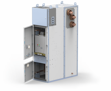
Withdrawable Switchgear
Withdrawable MV switchgear enables for the withdrawal of specific components such as the circuit breaker from the main enclosure without interfering with the operation of the rest of the switchboard, which is preferred over traditional switchgear that does not provide this benefit.
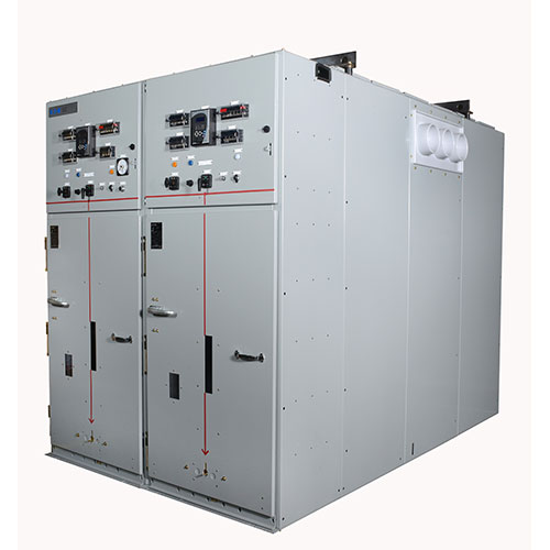
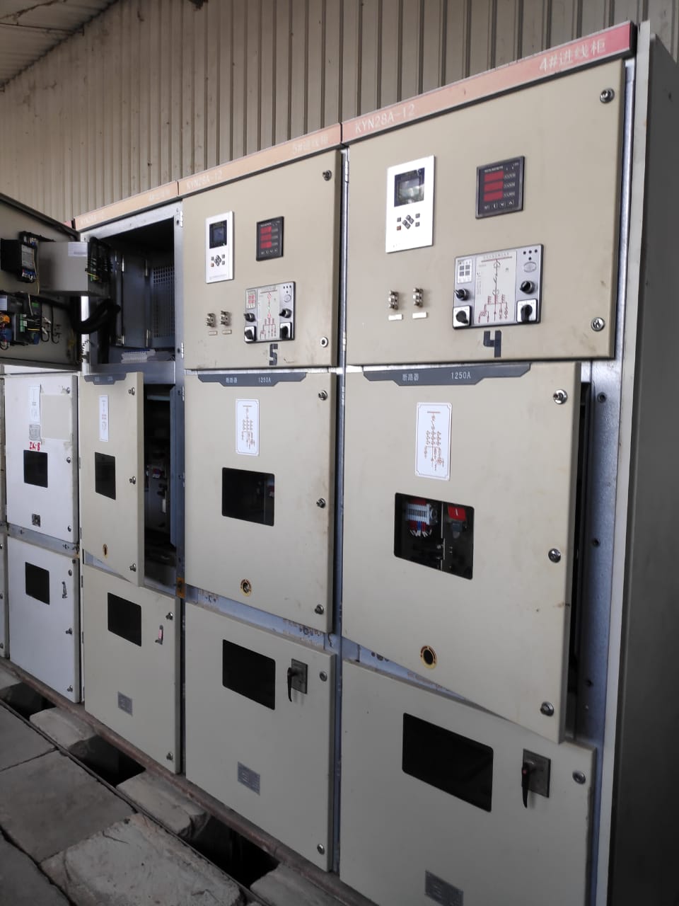
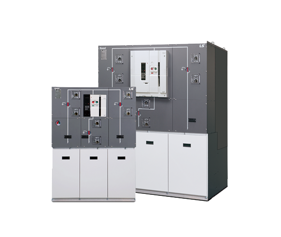
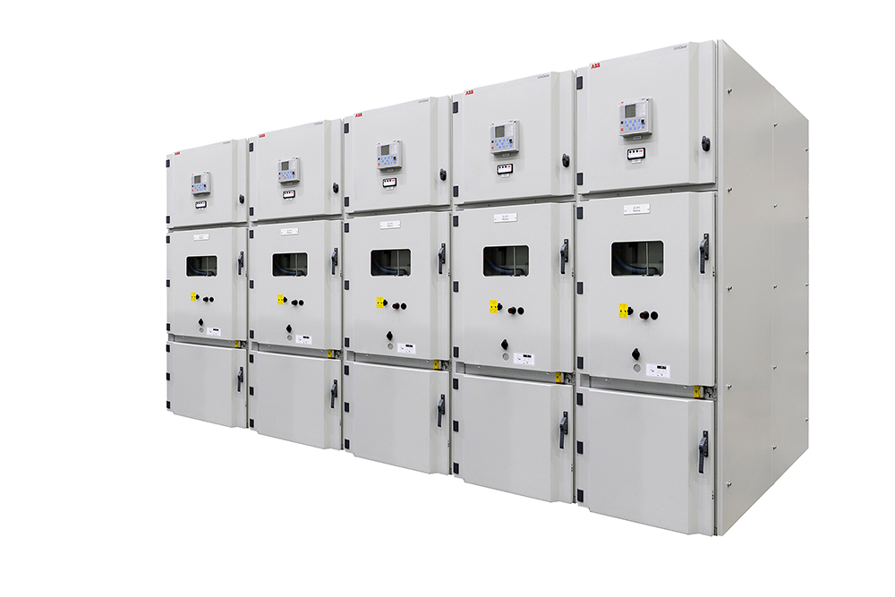
Power Distribution Cabinet
Switchgear is represented by a set of boxes, as you can see in the images above. Because switchgear combines numerous other electrical components, these boxes comprise the switch gears. For ease of use and safety, these components should be neatly organized.
A power distribution cabinet is machinery that provides electrical energy supply and redistribution. It also safeguards electrical power lines and overload and short circuit currents. The system can also measure power consumption if it is equipped with power meters.
The components of a power distribution cabinet include:
- A distribution switchboard.
- A power metering and distribution panel.
- A lighting panel.
- A residential distribution enclosure.
- Other types of electrical cabinets contain various electrical devices.
Busbars, circuit breakers, conventional relays, measuring instruments, and various other electronic components can be found inside a power cabinet.
By Types of Switchgear Enclosures
Switchgear enclosures protect your equipment from the elements. Fiberglass, steel, concrete, and aluminum are common materials preferred for enclosures. These enclosures keep the electric system inside from being damaged or harmed.
By Application
- Outdoor substations are large, and they are better suited for places with huge spaces.
- Indoor substations are better suited for areas with insufficient space for building substations.
- Industrial electrical switchgear is for companies that require bulk amounts of electricity like textile manufacturing industries, retail industries, etc.
- Commercial switchgear is used in supermarkets, shopping malls which require moderate amounts of electricity.
- Distribution cabinet usually contain low voltage equipment, so they are used in places that do not require much electricity. Households, road lighting are some applications of distribution cabinets.
What is Switchgear Construction
-
Interrupting Devices
Fuse
A fuse is a device that shuts down excessive current flow. When a high current is applied, the temperature rises and an electrical wire melts, thus halting the current flow.
Fuse and switch are often used in medium-voltage switchgear applications to provide overcurrent protection and the ability to open and close the circuit.
Vacuum Circuit Breaker
A vacuum circuit breaker is a type of high voltage circuit breaker in which arc interruption occurs within sealed vacuum bottles. The vacuum allows the arc to be swiftly extinguished, lowering arc energy. Vacuum circuit breakers can interrupt far higher voltage faults and take up far less space than air circuit breakers.
Vacuum Fault Interrupter
A vacuum fault interrupter serves as both an overcurrent protection device and a load break switch, obviating the need for a separate fuse and switch.
Switches
- Oil Switch
An oil switch is a switch that is soaked in oil. Since oil insulation provides a small, low-profile cover, these switches are widely utilized in pad-mounted switchgear.
- Air Switch
A switching device that uses air as a dielectric is known as an air switch. Air switches have lesser interrupting ratings than oil or vacuum switches and are easier to disconnect. Air switches are cheaper than oil and vacuum switches.
- Vacuum Switch
A vacuum switch is an electrical switch that interrupts the passage of electricity inside sealed vacuum bottles. The ensuing arc can be rapidly quenched thanks to the vacuum. Vacuum switches take up less room than air or oil switches, and they can handle higher voltages.
Control systems
In switchgear systems, instrument transformers (current and voltage transformers) are used to measure electrical parameters for protection and metering.
- Current Transformers
A current transformer is an equipment transformer in which the secondary current is nearly proportional to the main current and has a phase difference of less than one degree (CT).
- Voltage Transformers
A voltage transformer (VT) is an instrument transformer in which the secondary voltage is nearly proportional to the primary voltage and is phrased differently by around zero degrees.
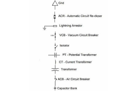
- Associated Circuitry
Electrical switchgear is composed of devices that switch and protect, such as switches, fuses, isolators, circuit breakers, protective relays, control panels, lightning arrestors, current transformers, potential transformers, auto reclosers, and other related equipment.
MV Switchgear Installation Process
Let’s take a look at how medium voltage switchgear equipment is installed.
It is imperative to take extra care during the installation procedure to safeguard the safety of all employees. The following items are necessary for switchgear installation:
- Personal protective equipment (PPE) is required for all employees and laborers.
- Measuring tape and setting out markers
- Drilling equipment
- Mobile crane or chain block
- Hand tools
- Electricians toolbox
Switchgear Installation Procedure
Ascertain that the concrete bases and foundation trenches provided for the installation of switchgear equipment are built in accordance with an approved design and the switchgear manufacturer’s drawing. Also, make sure that slots for bolts and passage cable provisions are procured as needed.
The panel should be installed in line with the placement and arrangement of MV switchgear panels as provided by the drawing plans, schematics, and coordination diagrams.
On units and components, remove the temporary channels and mounts from the main distribution board. Ensure that the trenches and covers used for power and control cable installation are in conformity with authorized plans. Also, make certain that the equipment you’re using is strong enough to support fixings and sleeves for the passage of cables that are to be built into the foundation bases as provided.
Place the switchgear panels on concrete foundations next. Install all incoming and outgoing cable supports, cable ends, and termination fittings for power and control cables. Tighten the electrical connectors and terminals to the torque tightening values specified by the electrical switchgear company.
The wiring should be made in front of the terminal board with no active metal visible. Ferrules will be used to terminate the wires. Wiring should be neatly organized on master terminal boards, with appropriate numbered strips and cartridge style fuses installed wherever necessary. All control wiring must be appropriately encased and protected in specialized trunking.
Setup the relays, timers, and other components as per the manufacturer’s instructions. Install the fundamental operating instructions for main distribution boards, including control and key interlocking sequences and emergency procedures for security reasons.
Installation of a Panel Board
Install panel boards and accessories in accordance with the authorized construction drawings and the manufacturer’s installation instructions.
Check the panel structure and component and wire arrangement with approved schematic diagrams. Unless otherwise specified on the approved coordinated equipment location plan, mounting heights must be 1800 mm above the finished floor.
The box is large and robust, with little distortion. Install flush panel boards flush with the wall finish. After meggering, terminate the wires to panels and inspect the cable terminations for tightness—complete earth terminals of all components and their related connections.
After balancing panel board loads, type the directory to indicate installed circuit loads. Before you install anything, be sure you get consent.
Switchgear Maintenance
By now, we have finished installing switchgear. The next step is maintenance. If the switchgear is placed in an air-conditioned environment, well ventilated, and clean, it does not need frequent maintenance, but certain inspections must be made from time to time. Inspections usually include:
- Checking interlock operations
- Identifying contact wear
- Keeping an eye on the overload settings
- Examining the fuse sizes used
- Keep an eye for signs of overheating.
- Examine the switchgear components for any signs of corrosion or grime.
- Inspect alignment, groundings, and connections.
- Look for signs of dampness, corrosion, or damage on electrical and mechanical parts.
- Test protective relays and circuit breakers
- Detection of ground faults and resistance testing
- Insulation resistance testing.
- Examine the current and voltage ratings to check that they meet the manufacturer’s specifications.
- Inspect electrical connections for high resistance.
Medium Voltage Switchgear Testing Process
- Travel and Velocity Test
An electrical current’s travel and velocity curves are measured during travel and velocity testing to determine interruption capability. - Functional Test
The circuit breaker is tested to see if it is working correctly. - Contact Timing Test
The time between the start of an order and the closure or splitting of the contacts is measured in contact timing testing. - Vibration Test
The circuit breaker’s vibration signature is measured during vibration testing. - X-Ray Test
X-ray testing is used to assess the condition of components in closed assemblies. - Contact Resistance Test
The contact resistance between current-conducting parts is assessed during contact resistance testing. - Tightness Test
Tightness testing is the process of manually checking the tightness of breaker connections. - Dynamic Contact Resistance Test
Contact resistance is measured repeatedly from start to finish in dynamic contact resistance testing. - AC Insulation Test
Insulation between open contacts, as well as line and ground, is measured during AC insulation testing. - Auxiliary Circuits Insulation Test
Insulation testing for auxiliary circuits measures the insulation of low voltage control circuits.
Test results should be checked and signed by the Q.C. Engineer, Site Electrical Engineer, and consultant.
Medium Voltage Switchgear Ratings
Overcurrent Protective Device Interrupt Ratings
The magnitude of current that the overcurrent protective device may safely interrupt without harming itself or the switchgear is called the interrupt rating.
Medium-voltage vacuum circuit breakers have symmetrical interrupt values ranging from 25 kAIC to 63 kAIC.
Switchgear Short-Circuit or Withstand Ratings
The highest amount of current that switchgear may safely let flow without causing harm to the switchgear is known as the short circuit current rating. This measures the busbars’ bracing and support, which allows them to withstand high power induced by the faults.
Short circuit current ratings for the 2-second rating vary from 25 kA to 63 kA symmetrical, and 40 kA to 101 kA asymmetrical for the 10-cycle rating, according to ANSI regulations.
Conclusion
Electricity has become an inextricable part of modern life. Electricity, as valuable as it is, nevertheless poses a risk. As a result, various precautions and safety requirements should be followed when dealing with it. Electricity must be used more efficiently and safely, therefore necessitating the use of switchgear.
Consider our services if you’re seeking medium voltage switchgear manufacturers who meet all safety requirements and are up to standards.