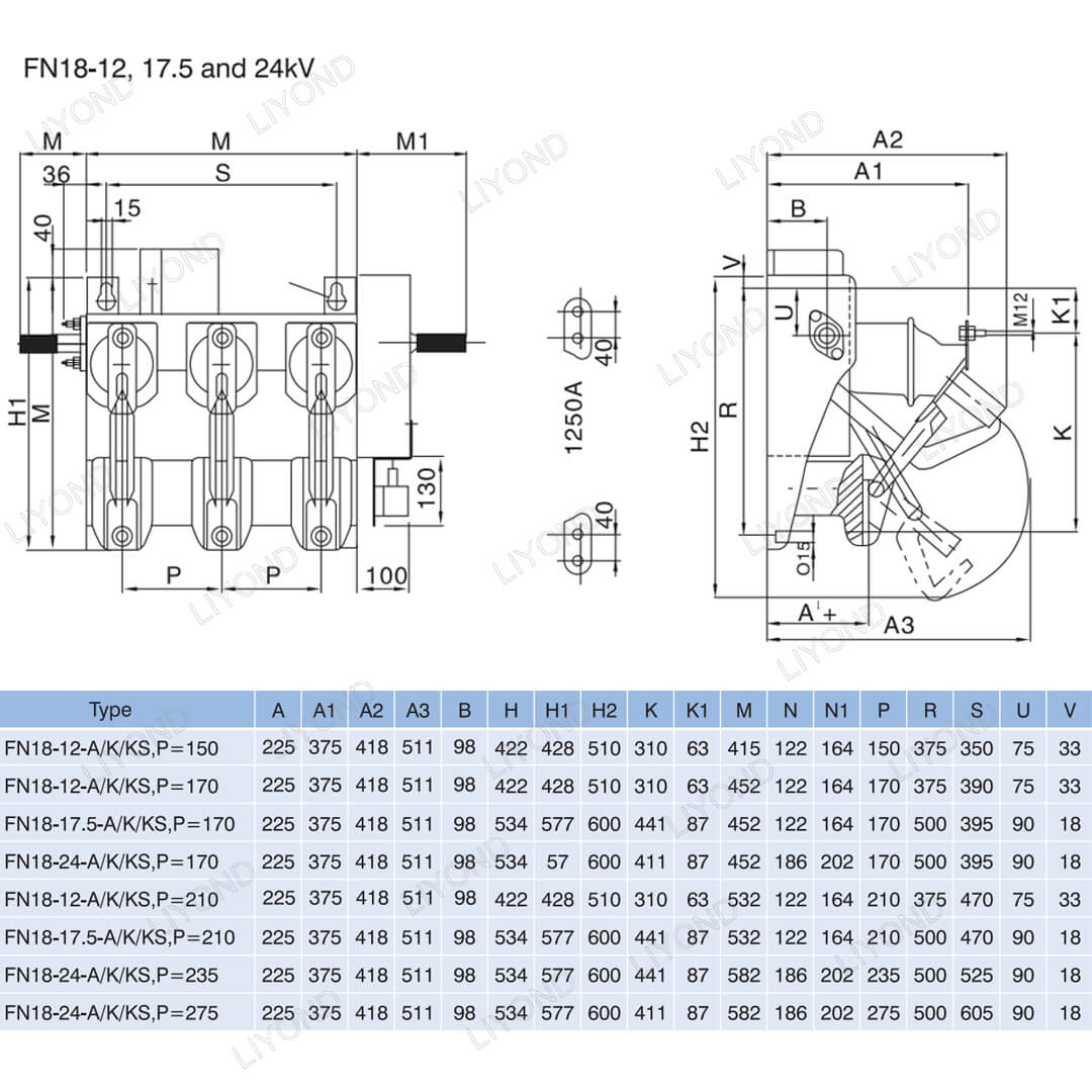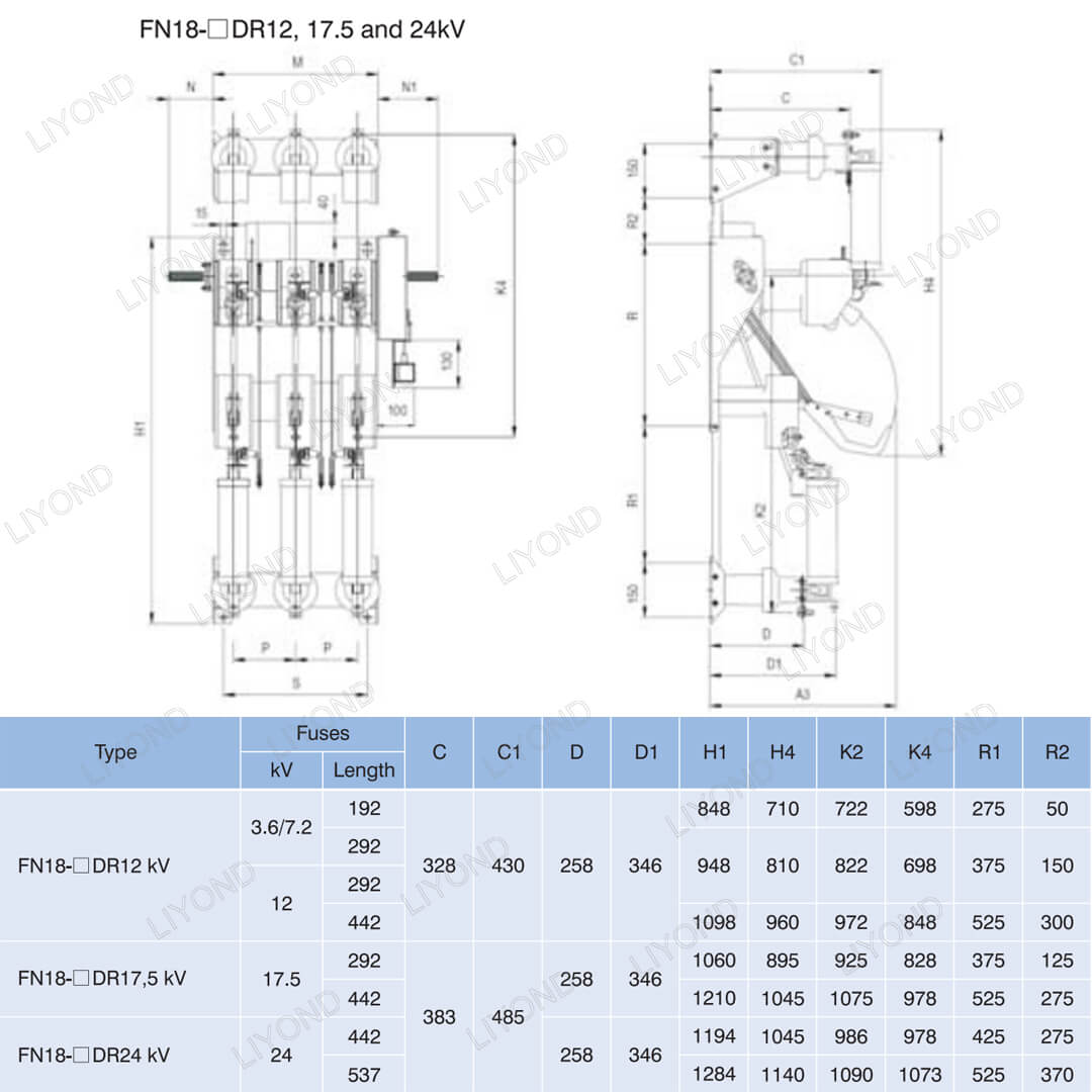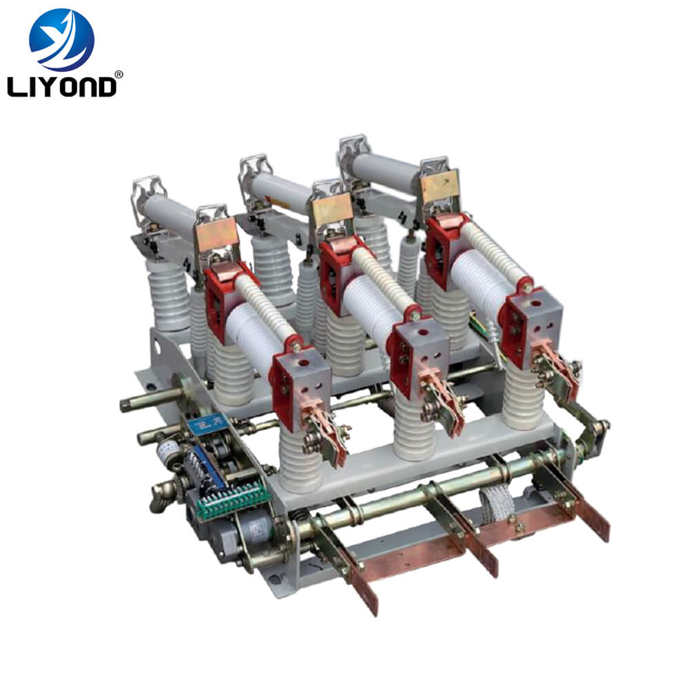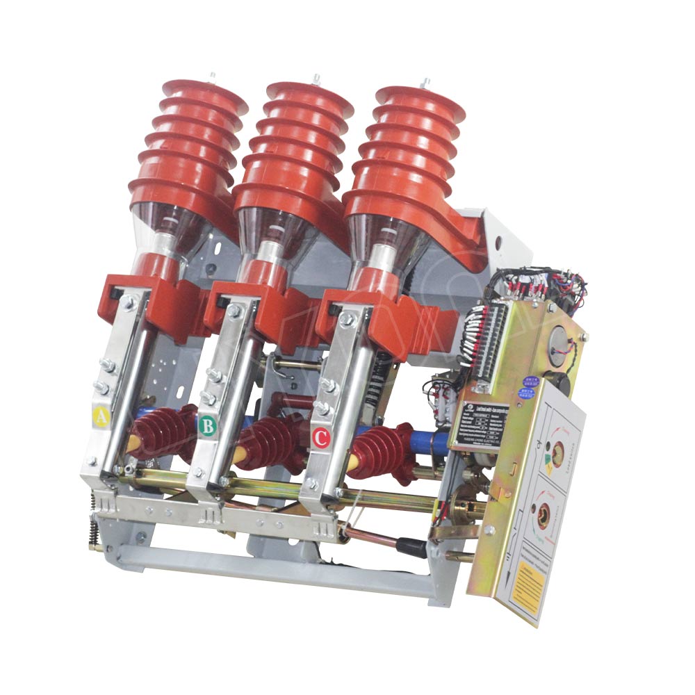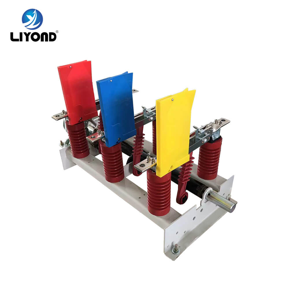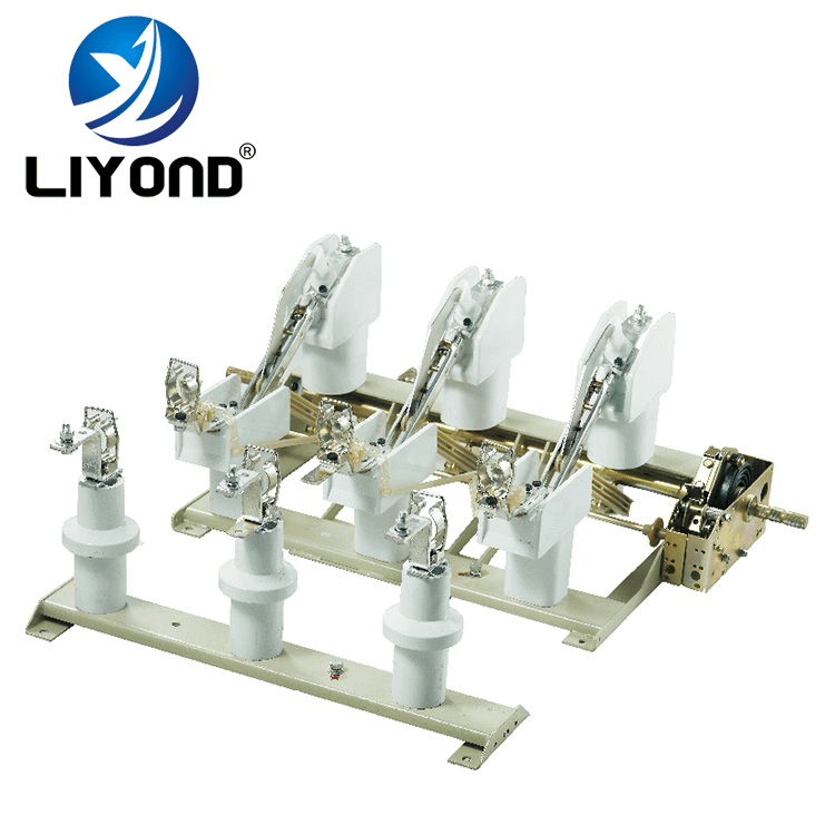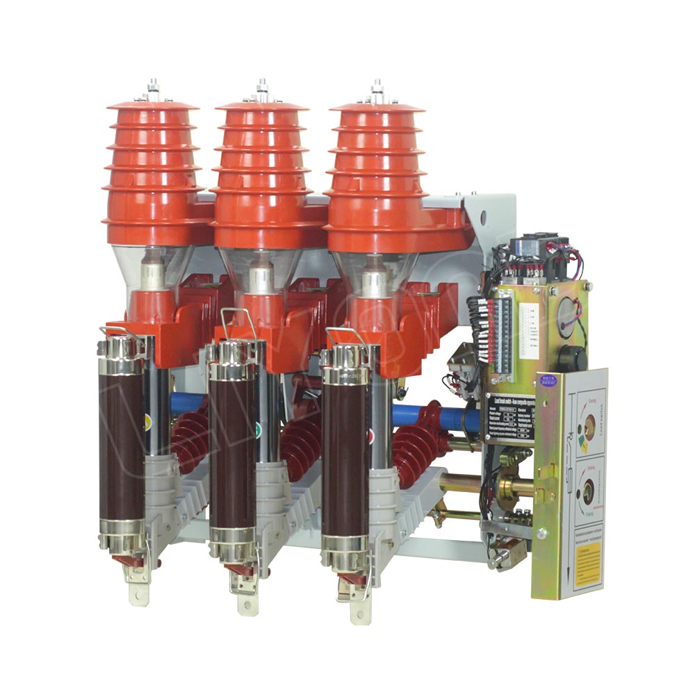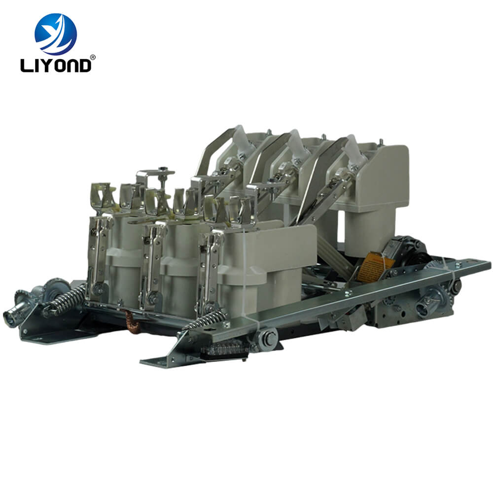
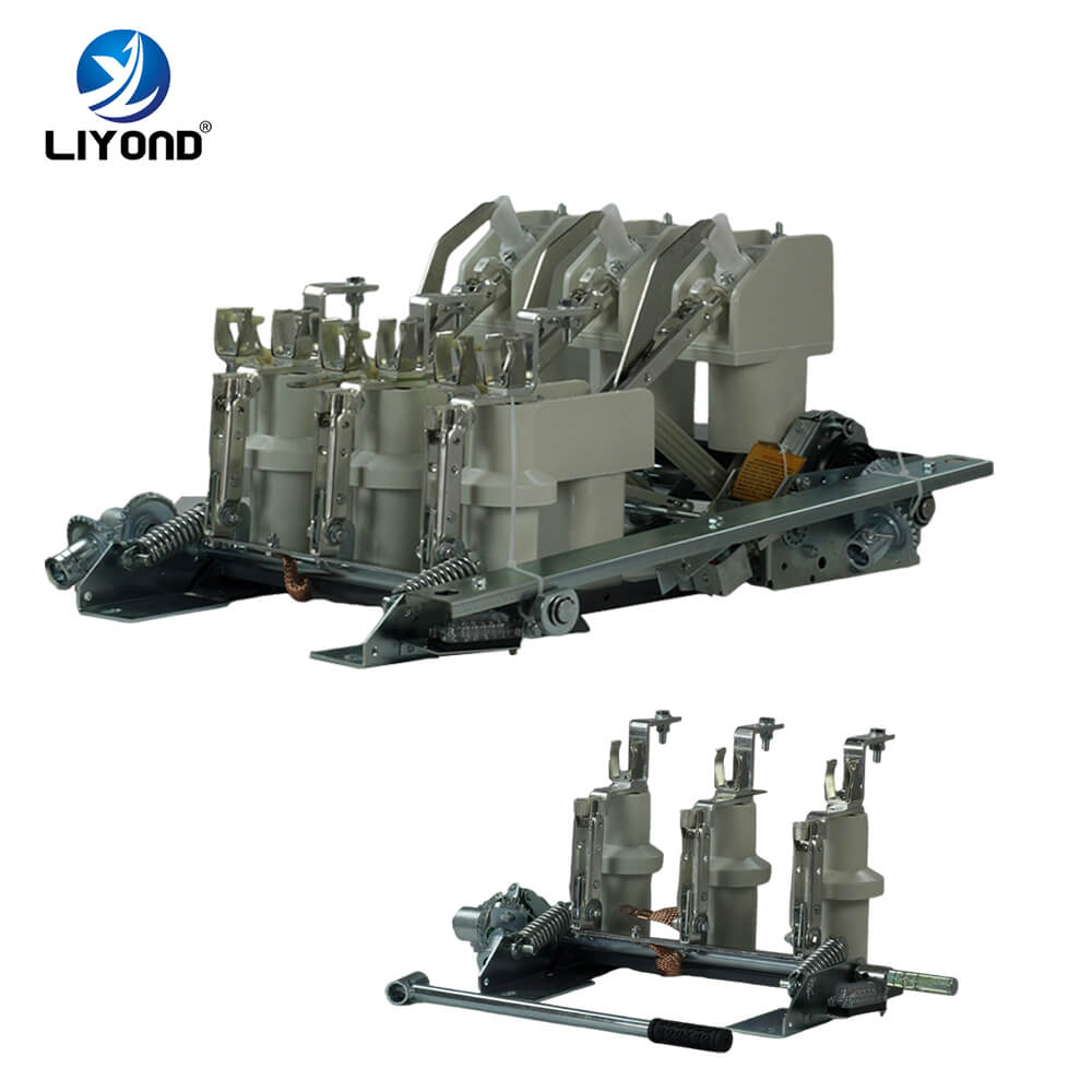
FN18-口is a general purpose, three-pole, load break switch that offers switchgear owners and assemblers the advantages of an advanced interrupting technology and proven, dependable performance in a compact design. The switch is available to switchgear assemblers as a building block for metal-enclosed and pad-mounted switchgear applications in ratings from 12-40.5 kV.
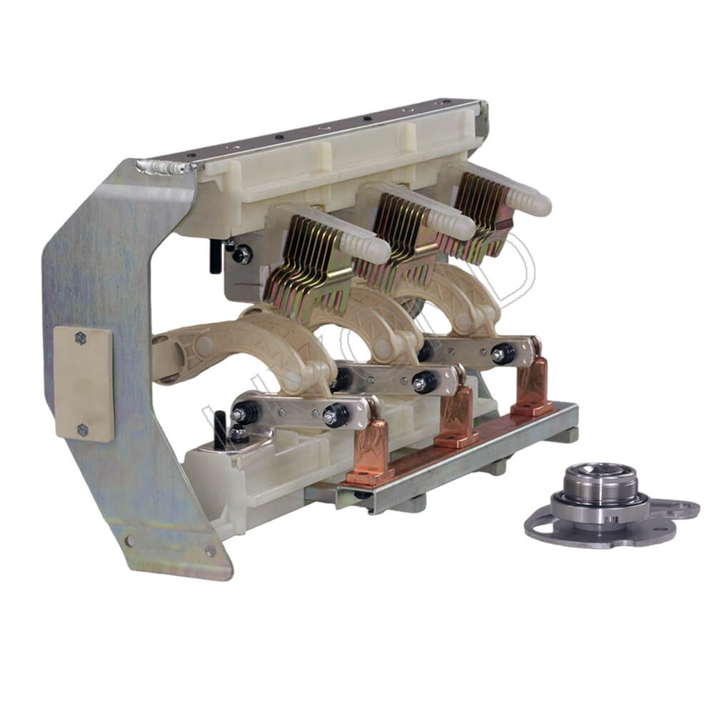
The standard FN18 switch includes a heavy-duty steel frame with stand-off insulators, a unique puffer-type arc extinguishing system, an operating mechanism and current-carrying components, including blade-type interrupters with cast hinges and jaw connectors.
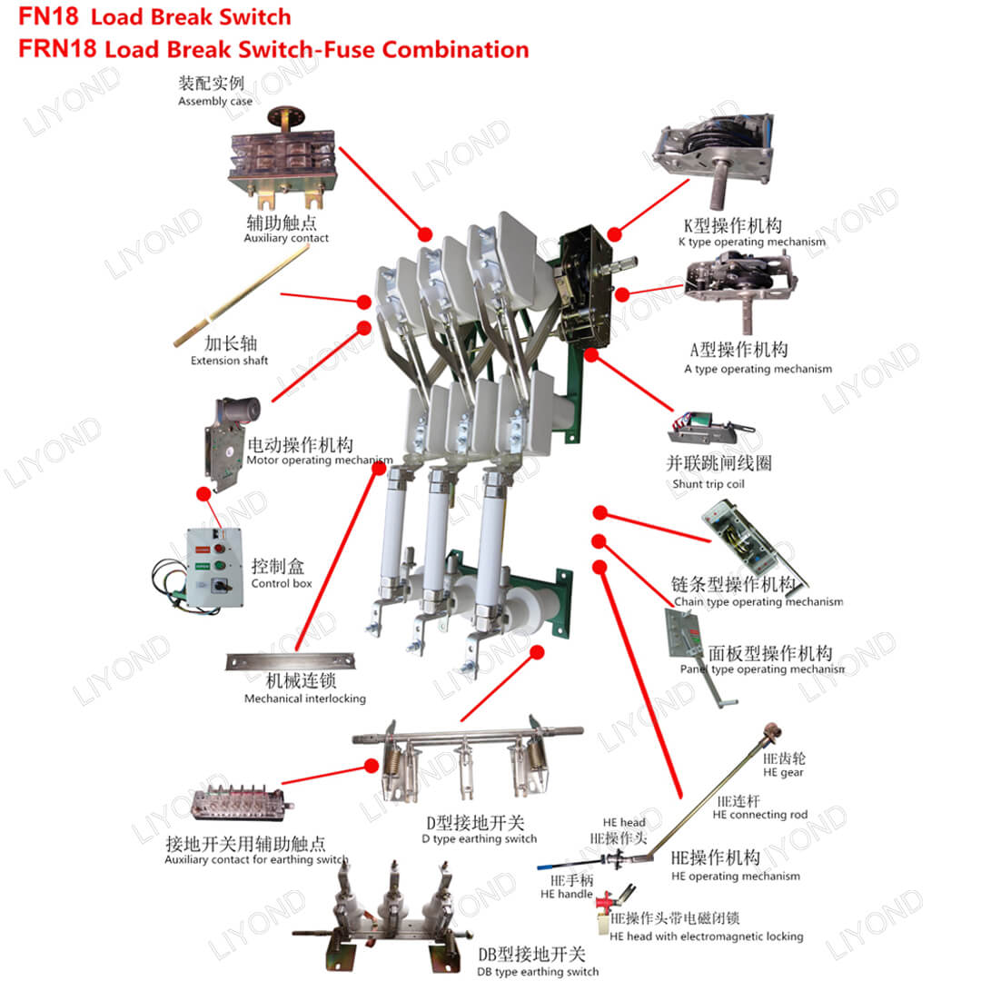
Optional accessories and features include a variety of operating handles, a motor operator, auxiliary switches, a shunt trip device, fuse bases, mechanical fuse tripping, grounding switches, mechanical door interlocking and key interlocking.
| Rated voltage | Unit | 12kV | 17.5kV | 24kV | 36kV | 40.5kV | |||||||||||
| Rated current | A | 400 | 630 | 1250 | 400 | 630 | 1250 | 400 | 630 | 1250 | 630 | 800 | 1000 | 630 | 800 | 1000 | |
| Max. rated current | A | 400 | 630 | 1250 | 400 | 630 | 1250 | 400 | 630 | 1250 | 630 | 800 | 800 | 630 | 800 | 800 | |
| Short circuit making capacity | KA peak | 67 | 50 | 50 | 50 | 50 | |||||||||||
| Peak withstand current | KA peak | 82 | 82 | 82 | 66 | 66 | |||||||||||
| Short time current | 1 sec. | KA eff | 31.5
25 20 |
31.5
25 20 |
31.5
25 20 |
31.5
25 |
31.5
25 |
31.5
25 |
25
25 16 |
25
25 16 |
31.5
25 16 |
25 | 25 | 25 | 25 | 25 | 25 |
| 2 sec. | |||||||||||||||||
| 3 sec. | |||||||||||||||||
| Mainly active load breaking capacity 21 (test duty 1 and, IEC 60265-1( 265)) | A | 400 | 630 | 1250 | 400 | 630 | 1250 | 400 | 630 | 1250 | 630 | 800 | 630 | 800 | 630 | 800 | |
| Mainly capacitive breaking capacity (test duty 4, IEC 60265-1 (IEC 265)) | A | 150 | 45 | 80 | 50 | 50 | |||||||||||
| Mainly inductive breaking capacity cosφ=0.15 | A | 16 | 16 | 16 | 16 | 16 | |||||||||||
| Max. breaking capacity in co-operation with fuses IEC 62271-105(IEC 420 1990-11) | A | 1600 | 1600 | 1600 | 1600 | 900 | 900 | 300 | 300 | 300 | 300 | 300 | 300 | ||||
|
Power frequency withstand voltage 50 Hz 1 min. -to earth and between poles -across isolating distance |
kV | 42
45 |
45
60 |
55 70 |
80 88 |
95 120 |
|||||||||||
|
Impulse withstand voltage 1.2/50 μs – to earth and between poles – across isolating distance |
kV | 75
85 |
95
110 |
125 145 |
170 195 |
190 220 |
|||||||||||
| Pole distance | mm | 150, 170, 210 | 170, 210 | 170, 235, 275 | 360 | 360 | |||||||||||
|
Max. operating torque at: -closing K/A mech. -opening K/A mech. |
Nm | 115-120 Nm K-mech.120 Nm/A-mech. 3Nm |
80-100 Nm K-mech.80-100 Nm |
||||||||||||||
| Operating angle on the shaft | degree | 130 | 120 | ||||||||||||||
| Opening time | ms | 40-60 | 60 | ||||||||||||||