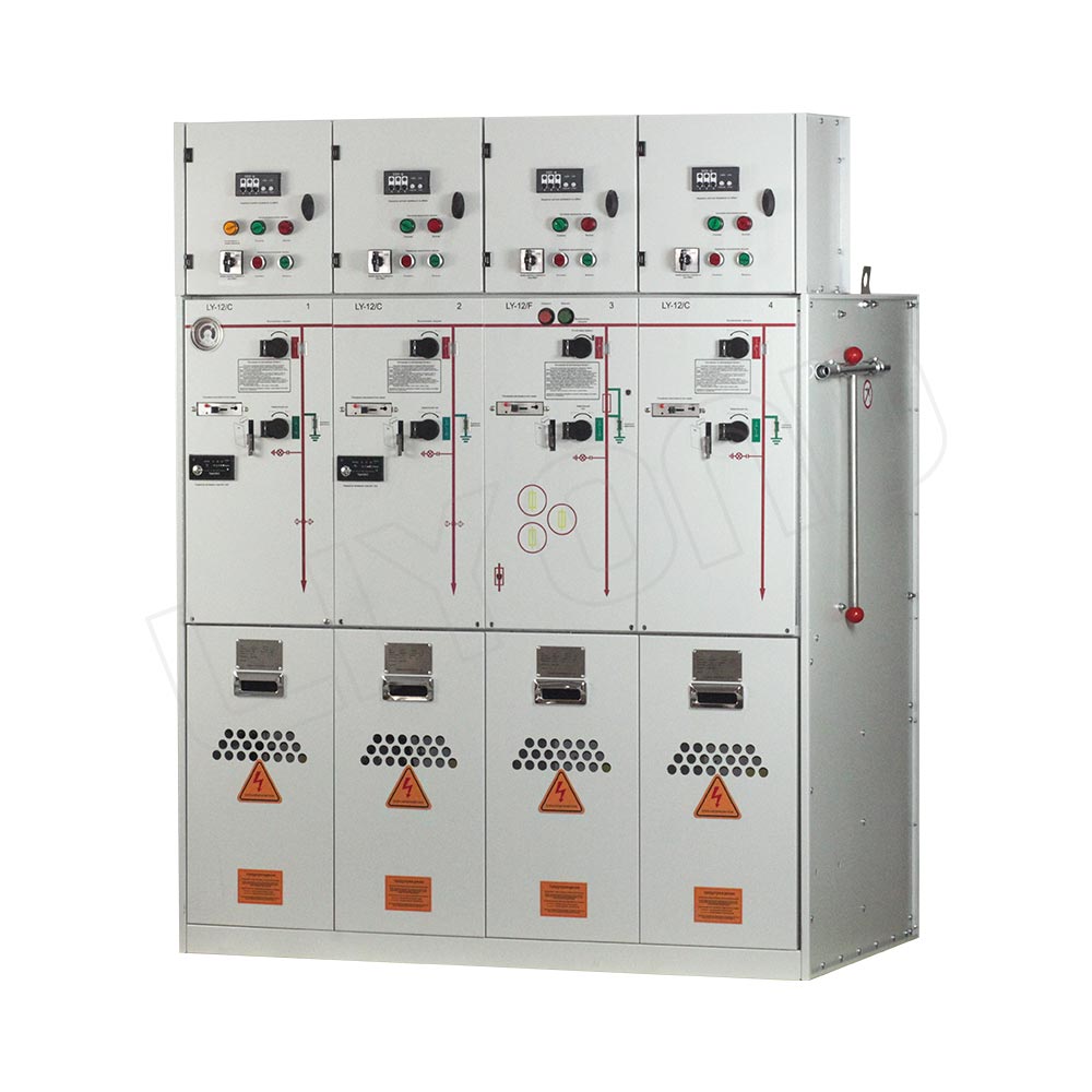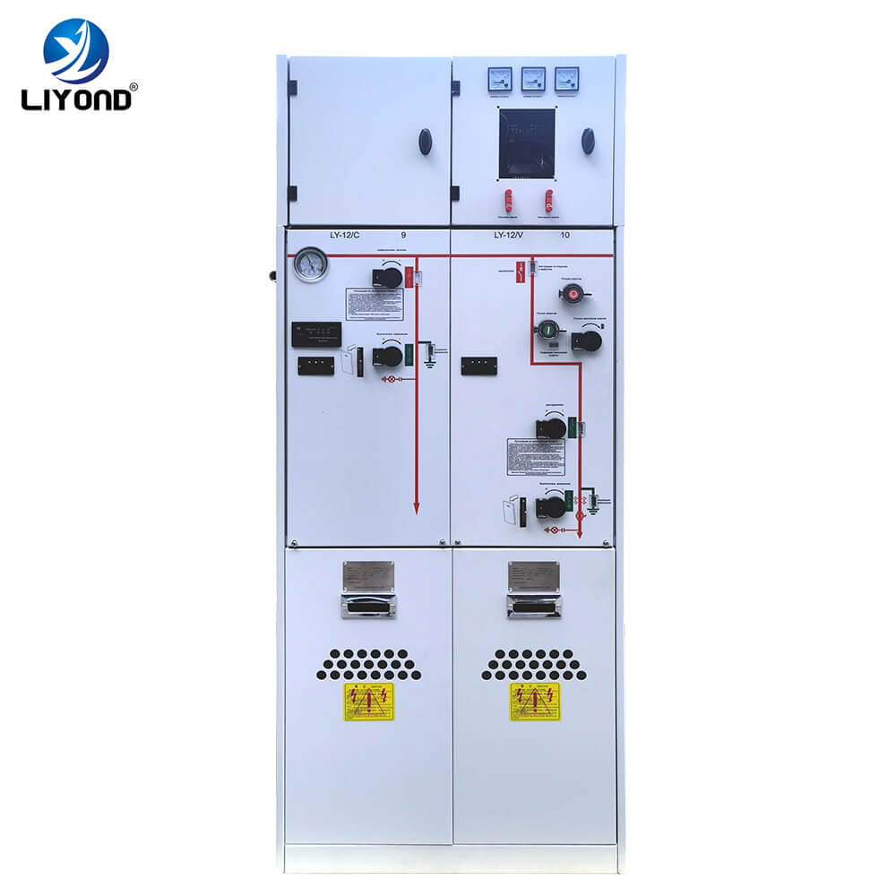
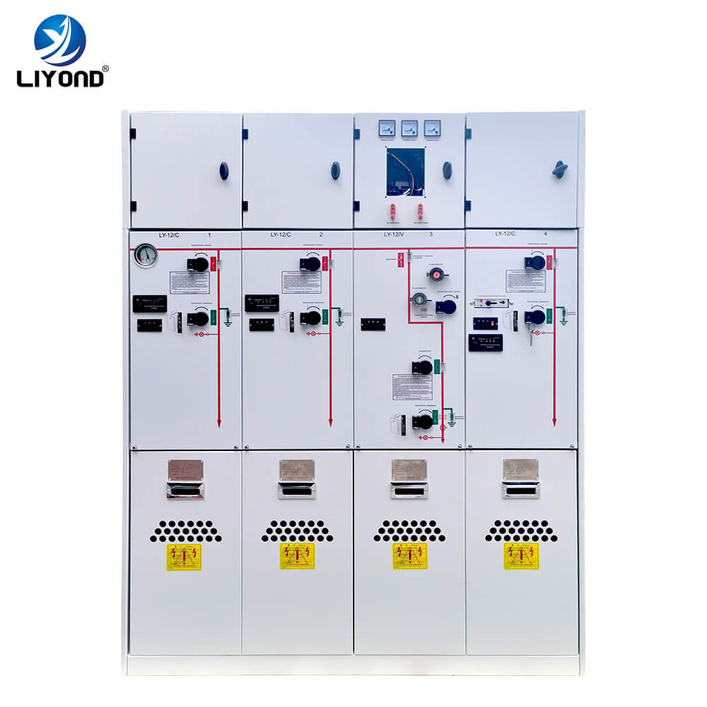
The gas inflatable cabinet produced by our company is suitable for 12kV power transmission and distribution system, a new type of switchgear that realizes control, protection, measurement, monitoring, communication and other functions, especially suitable for small power distribution facilities and high reliability requirements and underground, plateau, Coastal areas and other places where the natural environment and conditions are relatively harsh. At present, it is mainly used in areas with high reliability requirements, industrial and mining enterprises, substations, subways, light rail railways and other substations with tight land and limited space.
The conductive parts of high-voltage components such as circuit breakers, three-position switches, and load switches in the main circuit are centrally installed in a sealed cabinet-type stainless shell. Its biggest feature is that it is not affected by the external environment, and has high reliability. The place where the equipment can operate safely for a long time; followed by the size of the high-voltage components has been reduced to miniaturize the equipment. In addition, the components in the sealed casing are free of corrosion and rust, which eliminates the impact caused by this. In addition, the high-voltage components with stable performance and long electrical life can be used to achieve maintenance-free. or less maintenance requirements.
| Item | Unit | C module | F module | V module | |
| Load break Switch | Combination apparatus |
Vacuum switch |
Disconnecting/
earthing switch |
||
| Rated voltage | kV | 12 | 12 | 12 | 12 |
| Rated frequency | Hz | 50 | 50 | 50 | 50 |
| Power frequency withstand voltage (interphase/fracture) |
kV | 42/48 | 42/48 | 42/48 | 42/48 |
| Lightning impulse withstand voltage | kV | 75/85 | 75/85 | 75/85 | 75/85 |
| Rated current | A | 630 | * | 630 | 630 |
| Rated closed loop breaking current | A | 630 | |||
| Rated cable charged breaking current | A | 10 | |||
| Rated short-circuit making curemt (peak) | A | 50 | 80 | ||
| Rated peak withstand current | kA | 50 | |||
| Rated short time withstand current | kA/4s | 20 | |||
| Rated short circuit breaking current | kA | 31.5 | 20 | ||
| Rated transfer current | A | 1700 | |||
| Maximum current with fuse | A | – | 125 | ||
| Loop resistance | Ω | ≤300 | ≤600 | ||
| Mechanical life | Times | 5000 | 3000 | 5000 | 2000 |
*Depends on fuse rated current value.
1. Ambient air temperature: upper limit +40 °C lower limit -40 °C;
2. Air relative humidity: the daily average is not more than 95%, and the monthly average is not more than 90%;
3. Altitude ≤ 1500 meters (under standard inflation pressure);
4. The seismic intensity does not exceed 8;
5. Places without fire, explosion, serious pollution, chemical corrosion and severe vibration.
Special conditions
Manufacturer and end user must agree on special operating conditions that differ from normal operating conditions.
If particularly harsh operating environments are involved, the manufacturer and supplier must be consulted.
When the electrical equipment is installed above 1500 meters above sea level, it should be specified so that the pressure can be adjusted during manufacture. When this pressure is adjusted, the life of the switchgear itself has no significant effect.
The user must provide the following technical information when ordering:
1. Main circuit diagram, arrangement diagram and floor plan;
2. Schematic diagram of the secondary circuit of the switch cabinet;
3. Models, specifications and quantities of all electrical components in the switchgear;
4. If you need to set up a low-voltage box, it should be explained;
5. When the switch cabinet is used in special environmental conditions, it should be explained.