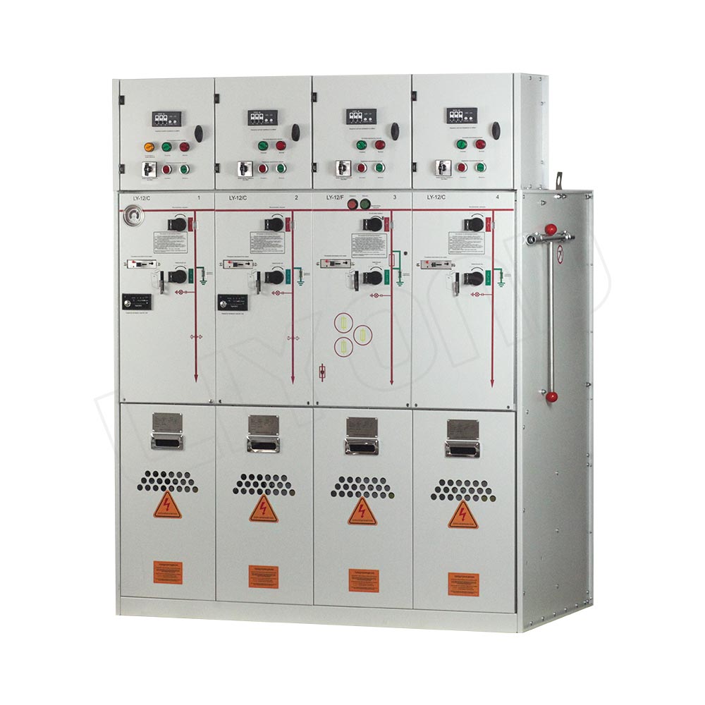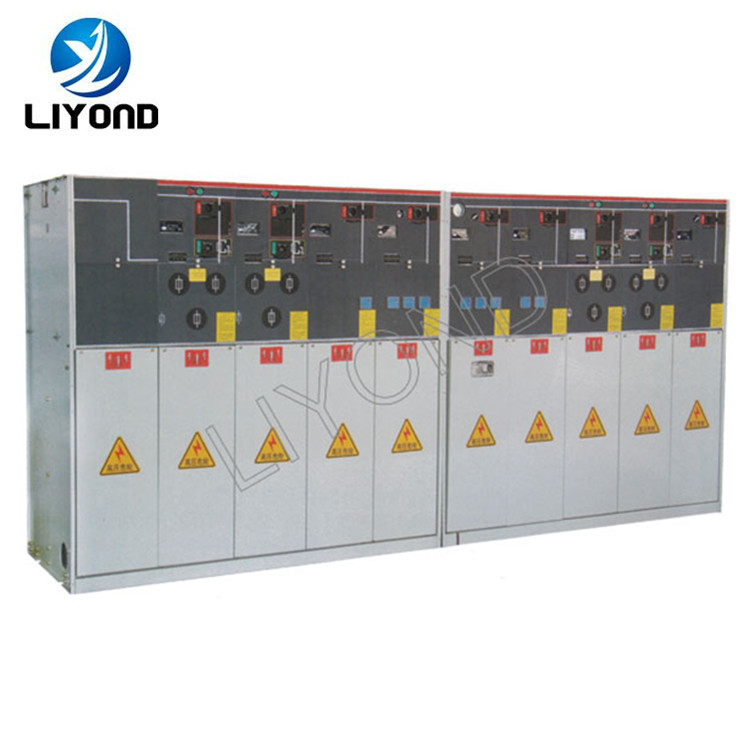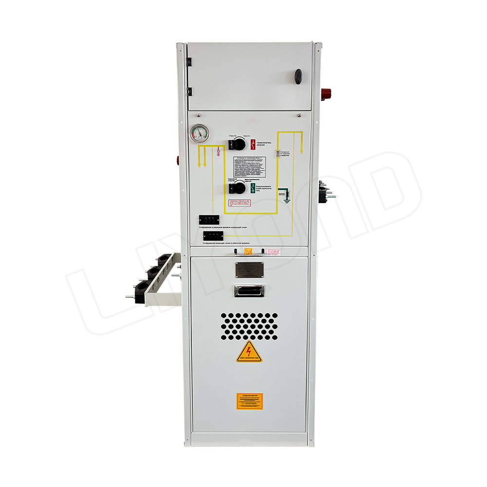
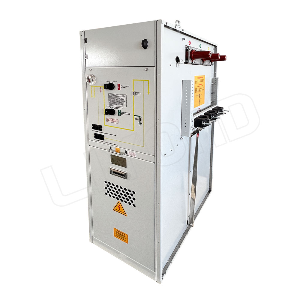
LYQF-40.5 Series gas insulated switchgear provide 10 standard combinations to meet the requirements of most 36 ~ 40.5kV distribution networks. LYQF-40.5 is compact switchgear that provides almost any combination of selected functional units.
LYQF-40.5 Series has interfaces and user interfaces, it provides a complete switching solutions for 36~40.5kV secondary distribution network.
The stainless stel gas chamber of LYQF- 40.5 Series is fled with SF6 gas, all live parts and switches are completely sealed and isolated from the outside. This fully sealed system keeps internal switches and all live parts free from external environmental changes, which ensures high relibility, personnel safety and maintenance- -free operation.
LYQF-40.5 is suitable for the customized use of switchgear in the following locations
1. Compact type secondary substation
2. Small industrial and mining enterprises
3. Wind power plants
4. Hotels, shopping centers, ffice buildings, commercial centers and so on
| Item | Unit | Unit C | Unit F | Unit V | |||
| load switch | earthing switch | load switch -fuse combination |
bottom earthing switch | vacuum circuit breaker | earthing switch /disconnect switches | ||
| Rated voltage | kV | 36/40.5 | 36/40.5 | 36/40.5 | 36/40.5 | 36/40.5 | 36/40.5 |
| Power frequency withstand voltage | kV | 70/95 | 70/95 | 70/95 | 70/95 | 70/95 | 70/95 |
| Isolation fracture | kV | 80/110 | 80/110 | 80/110 | |||
| Lightning impulse withstand voltage | kV | 170/185 | 170/185 | 170/185 | 170/185 | 170/185 | 170/185 |
| Isolation fracture | kV | 195/215 | 195/215 | 195/215 | |||
| Rated current | A | 630/630* | 200/200 | 630/630 | |||
| Breaking capacity | |||||||
| Active load | A | 630/630 | 200/200 | ||||
| Closed loop current breaking | A | 630/630 | 200/200 | ||||
| No-load cable charging | A | 20/21 | 20/21 | 50(C1) | |||
| Ground Fault | A | 60/63 | 60/63 | ||||
| Ground fault cable charging | A | 35/36 | 35/36 | ||||
| Divert current | A | 840/750 | |||||
| Short circuit breaking current | kA | 20(prospective) | 20(E1,S1) | ||||
| Closing ability | kA | 50/50(5 times) | 50/50(5 times) | 50(prospective) | 2.5(5 times) | 50/50 | 50/50 |
| Rating (electrical life) | E3/E2 | E2/E2 | -/- | E2/E2 | E2/E2 | E2/E2 | |
| 3s short-time withstand current | kA | 20/20 | 20/20 | Limited by high voltage fuse | 20/20 | 20/20 | |
| Internal arc classification | kA | 20/20 | 20/20 | 20/20 | |||
*Depends on the rated current value of fuse
1. Ambient air temperature: upper limit +40 °C lower limit -40 °C;
2. Air relative humidity: the daily average is not more than 95%, and the monthly average is not more than 90%;
3. Altitude ≤ 1500 meters (under standard inflation pressure);
4. The seismic intensity does not exceed 8;
5. Places without fire, explosion, serious pollution, chemical corrosion and severe vibration.
Special conditions
Manufacturer and end user must agree on special operating conditions that differ from normal operating conditions.
If particularly harsh operating environments are involved, the manufacturer and supplier must be consulted.
When the electrical equipment is installed above 1500 meters above sea level, it should be specified so that the pressure can be adjusted during manufacture. When this pressure is adjusted, the life of the switchgear itself has no significant effect.
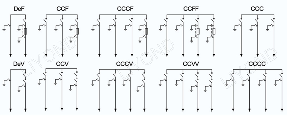
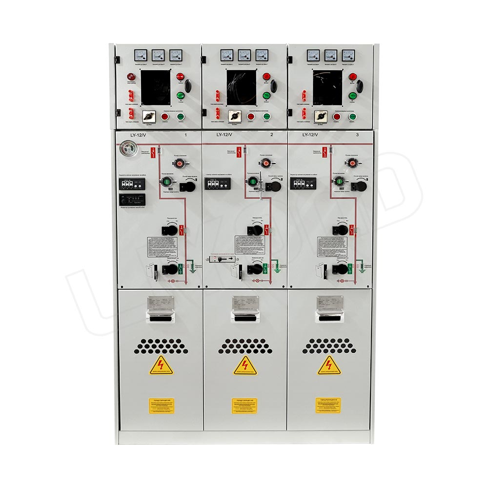
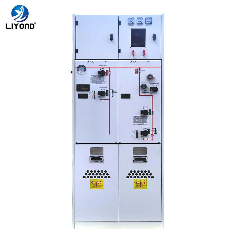
C-Load switch unit
D-Direct cable connection unit
De-Direct cable connection unit with earthing switch
F-Load switch-fuse combination
V-Vacuum circuit breaker unit
The user must provide the following technical information when ordering:
1. Main circuit diagram, arrangement diagram and floor plan;
2. Schematic diagram of the secondary circuit of the switch cabinet;
3. Models, specifications and quantities of all electrical components in the switchgear;
4. If you need to set up a low-voltage box, it should be explained;
5. When the switch cabinet is used in special environmental conditions, it should be explained.